Product Brief
VIE pneumatic clutch booster, part number 1608010‑FF61W102 with 102mm cylinder bore, is an OEM‑level replacement spare part specially designed for city buses, tour coaches and heavy‑duty passenger buses. Adopting mature pneumatic boosting principle, it converts compressed air into auxiliary thrust for clutch operation, delivering stable output and quick response for bus clutch system.
| Product Name | VIE Pneumatic Clutch Booster |
| Brand | VIE |
| Part Number | 1608010‑FF61W102 |
| Cylinder Bore | 102 mm |
| Product Type | Pneumatic Clutch Servo / Clutch Booster |
| Application | City Bus, Tour Coach, Heavy‑duty Passenger Bus |
| Compatible Chassis | Yutong, King Long, Higer, Dongfeng and other domestic bus chassis |
| Working Medium | Compressed Air |
| Main Body Material | Aluminum alloy valve body + painted steel air cylinder |
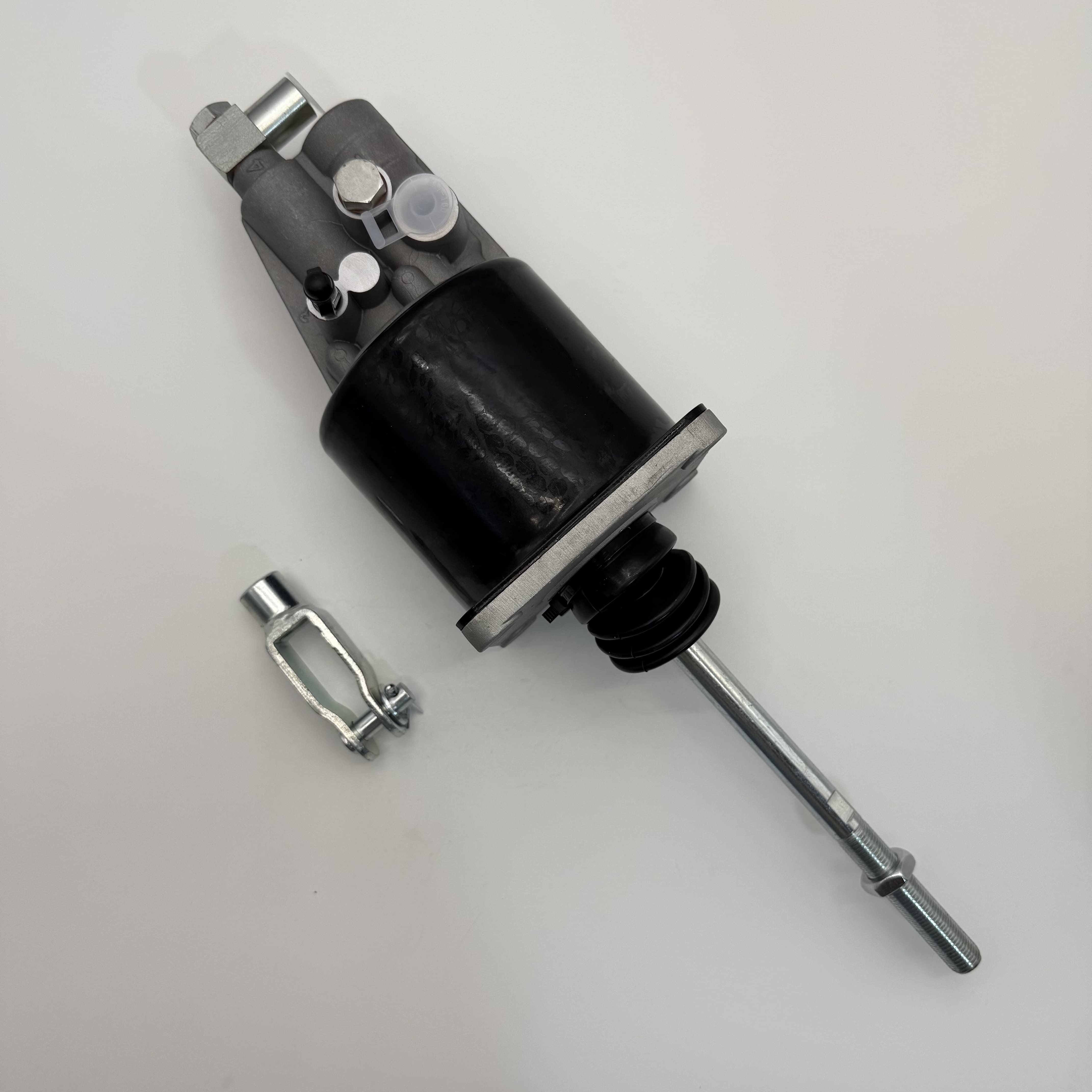
| Push Rod Type | Square‑head push rod |
| Dust Protection | Integrated rubber dust boot |
| Factory Test | 100 % air tightness & pressure test before shipment |
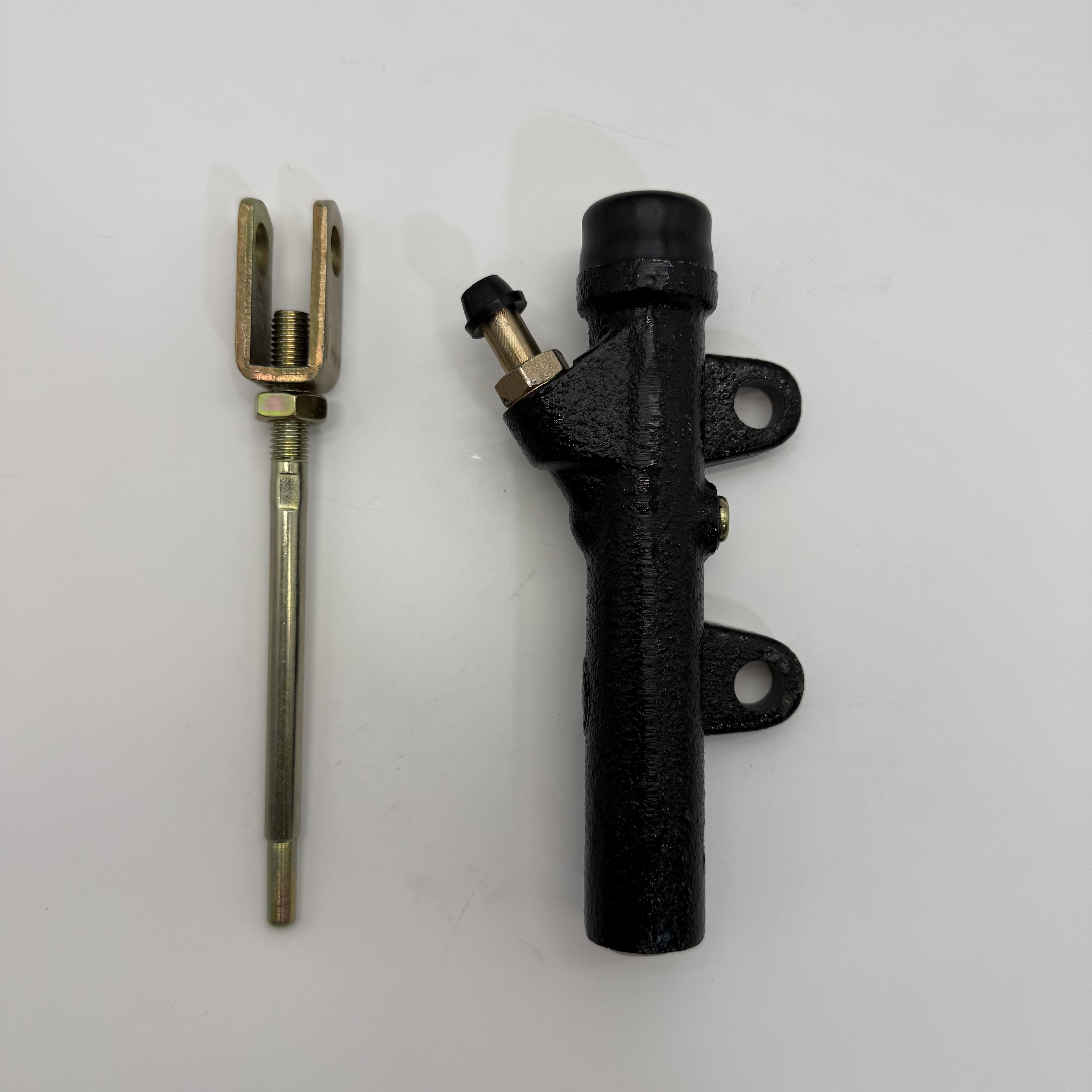
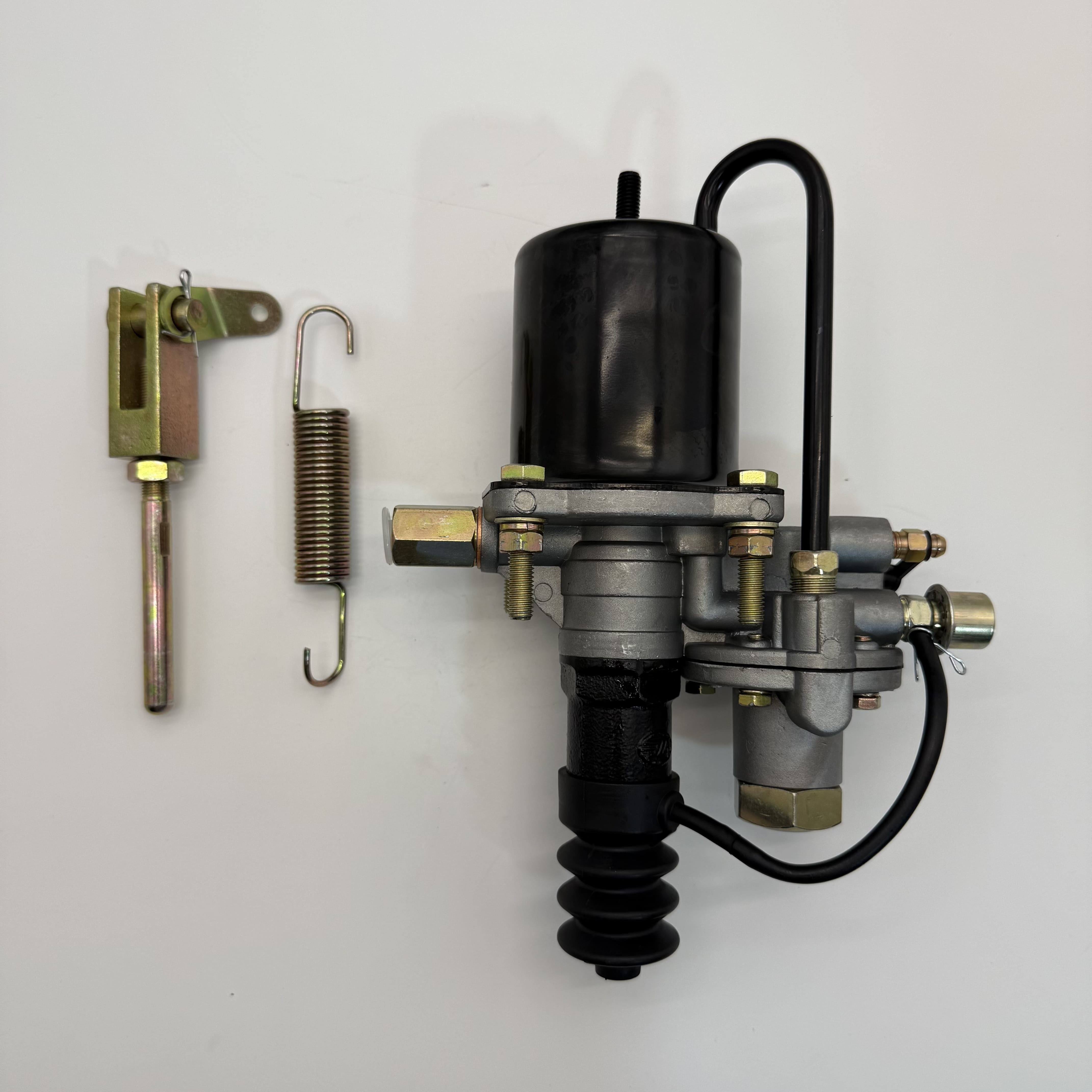
| Accessories | No extra accessories(original unit as picture) |
| Packing | Neutral individual carton box with foam cushion |
| Place of Origin | China |
| After‑sales | Warranty for manufacturing defects, quality inspection supported |
Product Features
Equipped with standard 102‑mm large cylinder bore, this booster owns strong load‑bearing capacity to satisfy high‑load working conditions of heavy passenger buses. It adopts aluminum alloy valve body and painted steel cylinder structure with square‑head push rod. Integrated rubber dust boot effectively blocks dust, sand and moisture to protect internal sealing parts. Every unit undergoes 100% air tightness and pressure test before delivery according to ISO/TS16949 quality standard. Flange mounting structure fits original bus chassis directly without modification. Stable air intake ensures sensitive and consistent clutch feedback.
Product Advantages
Excellent compatibility: direct OE replacement for city bus and tour coach, no chassis modification needed. Labor‑saving performance: pneumatic assistance lightens clutch pedal, solving heavy‑pedal problems on heavy‑duty buses. Reliable sealing performance lowers risks of air leakage and early failure, extending service life. Stable output under normal working pressure 0.6‑0.8MPa, resistant to frequent shift impact. Strict factory testing reduces aftermarket failure rate. Sufficient stock supports fast delivery, and warranty is available for manufacturing defects.

Installation Steps
1. Prepare installation tools, cut off vehicle air supply, release residual pressure inside pneumatic system to guarantee operation safety.
2. Remove old clutch booster, disconnect air pipelines and hydraulic pipelines, clean all connecting ports to prevent dirt entering system.
3. Align flange of new VIE clutch booster with chassis mounting position, tighten mounting bolts symmetrically to standard torque.
4. Connect air pipelines and hydraulic pipelines correctly, make sure all joints are tightly sealed without looseness.
5. Adjust square‑head push rod length to calibrate clutch working stroke, guarantee complete separation and firm engagement of clutch.
6. Restore vehicle air source, start engine, press clutch pedal repeatedly to check air leakage, oil leakage and abnormal vibration.
7. Carry out gear‑shift test under idling and low‑speed condition. Confirm clutch works normally and finish installation.
Precautions
1. Installation shall be completed by professional maintenance personnel; improper disassembly and assembly may cause air leakage and function failure.
2. Double‑check part number 1608010‑FF61W102 and 102mm cylinder bore before installation to avoid model mismatch.
3. Keep pipeline interfaces clean during installation. Do not let debris enter air circuit or hydraulic circuit to avoid blockage and component damage.
4. Do not over‑tighten or under‑tighten mounting bolts. Uneven bolt force will result in housing deformation and air leakage.
5. Push‑rod stroke must follow OEM specification. Excessive stroke causes clutch burning; insufficient stroke leads to incomplete separation.
6. Keep working air pressure within 0.6‑0.8MPa; maximum pressure shall not exceed 1.0MPa. Over‑pressure operation will damage internal seals.
7. Regularly inspect pipeline tightness and aging condition of rubber dust boot in daily service, replace vulnerable parts timely.
8. Stop using immediately if you find weak assist, slow response or air leakage, carry out inspection to eliminate potential driving risk.