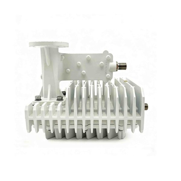
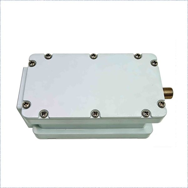
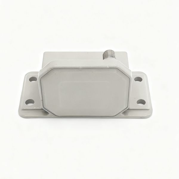
VSAT KU Band Block Up Converter (BUC) - ST-Tx6W
VSAT RF Assembly: LNB (950-1700MHz In) & BUC (13.75-14.5GHz Out) - 58dB Small Signal Gain
Technical Specifications
| No. |
ITEM |
SPECIFICATION |
UNIT |
| K-1 |
Output Frequency Range |
13.75 ~ 14.5 |
GHz |
| K-2 |
Input Frequency Range |
950 ~ 1700 |
MHz |
| K-3 |
LO Frequency |
12.8 |
GHz |
| K-4 |
Noise Figure |
15[Max.] |
dB |
| K-5 |
10MHz External Reference Frequency sensitivity |
-15 ~ +5 |
dBm |
| K-6 |
Output Power (P1dB) |
+37.8[Typ.] (+25℃) |
dBm |
| K-7 |
IF Input VSWR |
2.0:1 |
/ |
| K-8 |
RF Shut off |
-70 |
dBm |
| K-9 |
In Band Spurious(Power +30dBm Output) |
-50 |
dBc |
| K-10 |
Out of Band Spurious (Power +30dBm Output) |
-50 |
dBc |
| K-11 |
(a) over any 2MHz Band (pk-pk) |
0.5 |
dB |
| K-12 |
(b) over any 125MHz Band (pk-pk) |
2.5 |
dB |
| K-13 |
(c) over any 500MHz Band (pk-pk) |
4 |
dB |
| K-14 |
Power Draw |
38[Max.] |
W |
| K-15 |
DC Voltage Range |
20 ~ 30 |
V |
| K-16 |
Weight |
880 |
g |
| K-17 |
Operating Temperature |
-40 ~ +60 |
℃ |
| K-18 |
RF Output VSWR |
2.0:1 |
/ |
| K-19 |
Small Signal Gain |
58[Typ.]/54[Min.] |
dB |
What is a Block Up Converter (BUC)?
A Block Up Converter (BUC) is a critical radio frequency (RF) device used in satellite communications (satcom) to transmit a signal from Earth to a satellite. Its primary function is to convert a lower frequency signal to a much higher frequency (microwave band) and amplify it with enough power to travel the vast distance to a geostationary or other satellite.
Think of it as the powerful "shouter" in a satellite link:
- Your modem creates the message (data)
- The BUC shouts this message on a very high-frequency channel so the satellite far away can hear it clearly
- The satellite's "ears" are its transponders
It is almost always used in conjunction with a LNB (Low-Noise Block downconverter), which performs the reverse function for receiving signals.
In a nutshell: BUC (Transmit) + LNB (Receive) = ODU (Outdoor Unit) in a VSAT antenna system.
How Does a BUC Work? (Key Functions)
A BUC performs three essential operations in sequence:
- Frequency Up-Conversion: This is its core task. It takes an intermediate frequency (IF) signal coming from the indoor satellite modem (typically in the L-band, e.g., 950-1750 MHz or 1400 MHz) and mixes it with a stable, high-frequency local oscillator (LO) signal. This process shifts the IF signal up to the final radio frequency (RF) band used for satellite uplinks, such as Ku-band (14 GHz), Ka-band (30 GHz), or C-band (6 GHz)
- Power Amplification: The up-converted signal is very weak. The BUC contains a High-Power Amplifier (HPA), using technology like GaAs FET or GaN, to boost the signal power dramatically. Output power is a key specification, ranging from 2W (for small mobile terminals) to hundreds of watts (for large teleports)
- Filtering: Internal filters clean the signal, removing unwanted harmonics and spurious emissions generated during the up-conversion and amplification process to ensure a pure transmission that meets regulatory standards
Block Diagram & Signal Flow:
Satellite Modem (Indoor)
↓
IF Signal (e.g., 1400 MHz) + DC Power via Coaxial Cable
↓
**BUC (Outdoor on antenna)**
↓
1. **Up-Converter:** IF + LO → RF (e.g., 14.25 GHz)
↓
2. **Power Amplifier:** Boosts to, e.g., 8 Watts
↓
3. **Filter:** Removes unwanted noise
↓
RF Output to Feed Horn
↓
Transmitted to Satellite
BUC vs. LNB: A Quick Comparison