Product Description
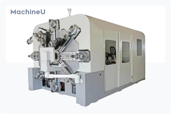
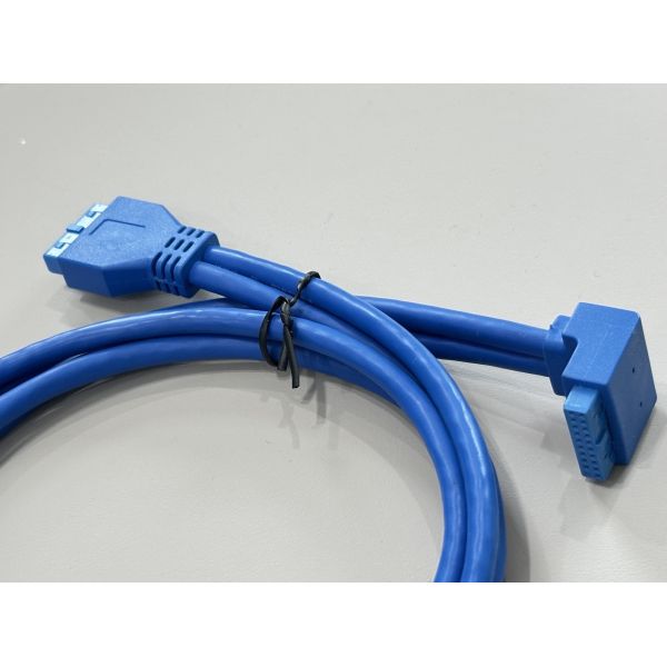
This USB 3.0 20-pin internal header connector cable is designed for high-speed data and stable power transmission between a motherboard and front-panel USB modules or custom PCB boards. The right-angle connector side saves space near the motherboard, helping cable routing in compact PC and server chassis. Stranded tinned-copper conductors and matched impedance design support up to 5 Gbps SuperSpeed USB performance with low signal loss.
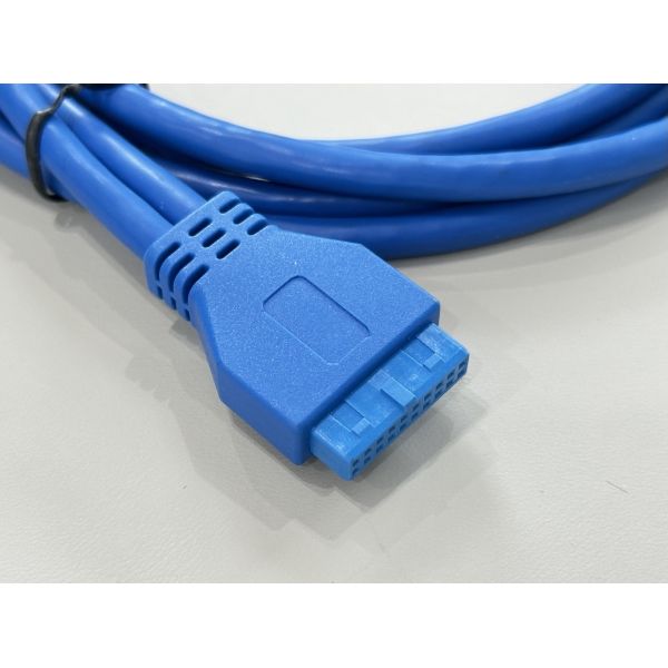
The molded housings protect the terminals from mechanical stress, while the flexible blue PVC jacket makes the cable easy to route around other components. Consistent pin pitch and precise terminal alignment ensure reliable mating with standard USB 3.0 header sockets. Custom wiring, different lengths and harness integration with other connectors can be provided according to project needs.

| Product type | USB 3.0 internal header connector cable |
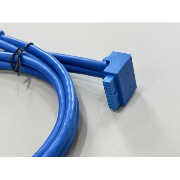
| Connector A | 20-pin USB 3.0 header connector, right-angle type |
| Connector B | 20-pin USB 3.0 header connector, straight type |
| Pin count | 20 pins per connector |
| Interface standard | USB 3.0 / USB 2.0 backward compatible |
| Data rate | Up to 5 Gbps SuperSpeed transmission |
| Cable length | 1.0 m (custom length available) |
| Conductor | Tinned copper wire, stranded |
| Wire gauge | 26–28 AWG (per design) |
| Insulation & jacket | PVC insulation, outer jacket blue |
| Operating voltage | 30 V DC max |
| Operating temperature | -20 °C to +80 °C |
| Flame rating | UL-style cable, RoHS compliant |
| Application | PC motherboard to front-panel PCB, server chassis, industrial controller I/O |
| Customization | Length, pin-out, color, labeling and over-molding available |
Applications
Connecting PC or workstation motherboard USB 3.0 headers to front-panel USB ports
Internal USB link for servers, storage systems and embedded computers
Cable harnesses between USB expansion cards and custom I/O boards
OEM integration in industrial controllers, test equipment and communication devices
Precautions
Confirm the 20-pin header pin-out matches your motherboard and front-panel PCB before installation.
Avoid excessive bending near the connector over-mold; keep the bend radius larger than 10× cable diameter.
Insert and remove the connector by holding the plastic housing, not by pulling the cable.
Do not exceed the rated current and voltage on the power pins to prevent overheating.
Keep the cable away from sharp edges, high-temperature components and strong EMI sources for best signal integrity.