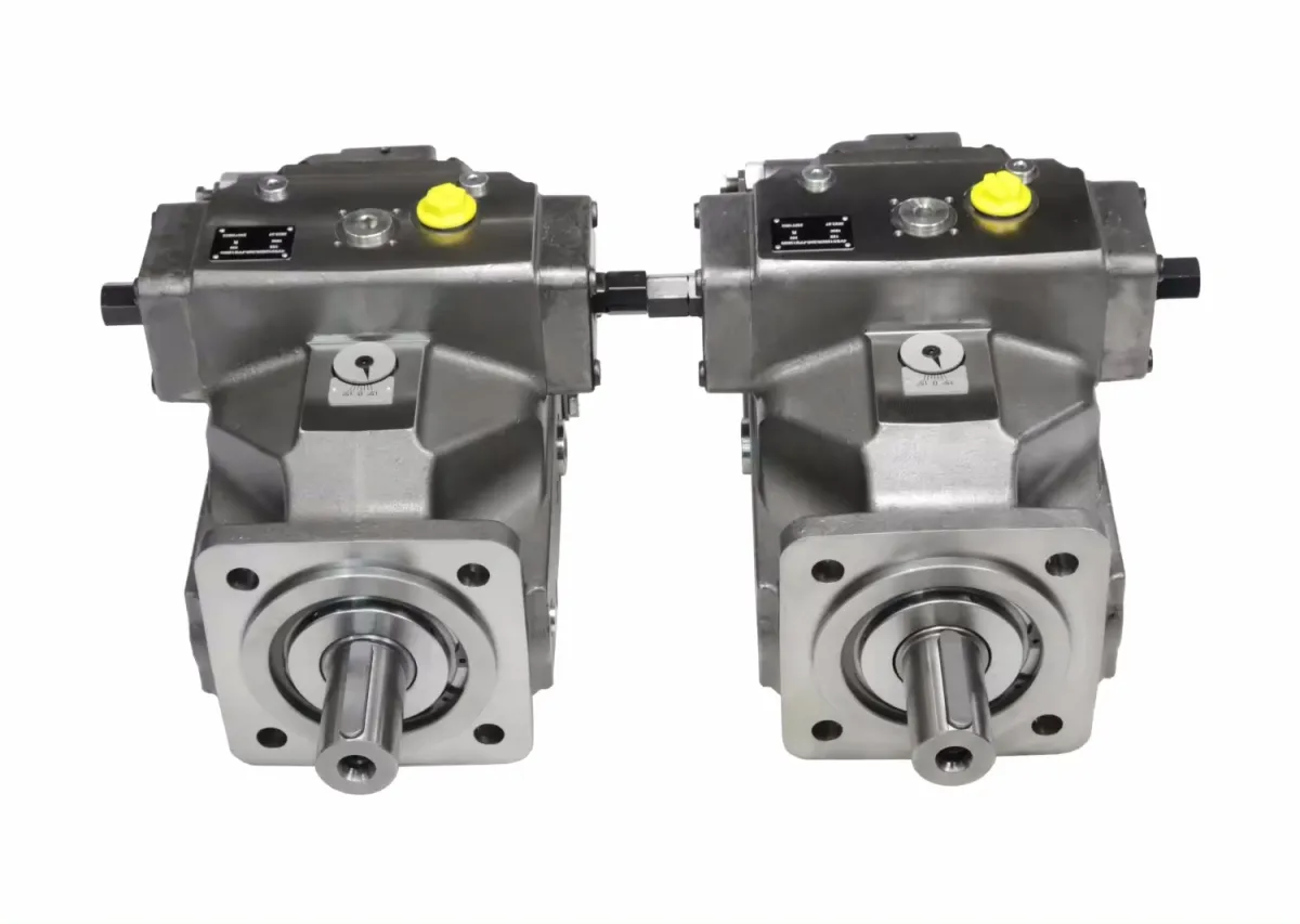
A4VSO355EO1/30L-PPB25N00 A4VSO355LR2/30L-PPB25N00 A4VSO500EO1/30L-PPB13N00 German Rexroth Mechanical Hydraulic Industrial Hydraulic Pump Imported Genuine Product
| Item | Specification |
| Brand Name | Rexroth |
| Pump Type | Piston Pump |
| Warranty | 1 Year |
| Place of Origin | Fujian, China |
| Connection Size | 1/4 inch |
| Max. Horsepower | 2 HP |
| Number of Stages | 1 Stage |
| Operating Pressure | 100 bar |
| Pressure | Other |
| Structure | Other |
| Material | Carbon Steel |
| Application | Construction Machinery |
| MOQ | 1 Piece |
| After-sales Service Provided | Line Support |
| Package | Wooden Case |
| Color | Customer's Request |

| A4VSO180LR2/30L-PPB13N00 |
| A4VSO180DRG/30L-PPB25N00 |
| A4VSO180DRG/30L-PPB13N00 |
| A4VSO180DFR/30L-PPB13N00 |
| A4VSO180LR2G/30L-PPB25N00 |
| A4VSO180LR2G/30L-PPB13N00 |
| A4VSO180DR/30L-PPB25N00 |
| A4VSO180DR/30L-PPB13N00 |
| A4VSO125EO2/30L-PPB25N00 |
| A4VSO125DFR/30L-PPB13N00 |
| A4VSO125EO2/30L-PPB13N00 |
| A4VSO125EO1/30L-PPB25N00 |
| A4VSO125EO1/30L-PPB13N00 |
| A4VSO125LR2/30L-PPB25N00 |
| A4VSO125LR2/30L-PPB13N00 |
| A4VSO125DRG/30L-PPB25N00 |
| A4VSO125DRG/30L-PPB13N00 |
| A4VSO125DFR/30L-PPB25N00 |
| A4VSO125LR2G/30L-PPB25N00 |
| A4VSO125LR2G/30L-PPB13N00 |
| A4VSO125DR/30L-PPB13N00 |
| A4VSO71EO2/30L-PPB25N00 |
| A4VSO71EO2/30L-PPB13N00 |
| A4VSO71LR2G/30L-PPB13N00 |
| A4VSO71EO1/30L-PPB25N00 |
| A4VSO71EO1/30L-PPB13N00 |
| A4VSO71LR2/30L-PPB25N00 |
| A4VSO71LR2/30L-PPB13N00 |
| A4VSO71DRG/30L-PPB25N00 |
| A4VSO71DRG/30L-PPB13N00 |
| A4VSO71DFR/30L-PPB25N00 |
| A4VSO71DFR/30L-PPB13N00 |
| A4VSO71LR2G/30L-PPB25N00 |
| A4VSO355EO1/30R-VZB13N00 |
| A4VSO355EO1/30R-VPB25N00 |
| A4VSO71DR/30L-PPB13N00 |
| A4VSO500EO2/30R-PPB13N00 |
| A4VSO500EO1/30R-PPB13N00 |
FAQ;
1. Special Scenario Troubleshooting
Q1: The pump operates normally on land but experiences cavitation when installed on a ship (rolling and pitching motion)—how to fix it?
A10: Shipboard cavitation is caused by oil level fluctuations due to rolling/pitching—solutions: ① Tank Modifications: Install anti-surge baffles in the hydraulic tank (vertical baffles every 30cm) to reduce oil sloshing; increase the tank volume by 50% (e.g., from 200L to 300L) to maintain a stable oil level during ±15° rolling; ② Suction Line Optimization: Route the suction line to the tank’s center (not side) and install a sump (10L capacity) at the suction port—ensures oil supply during extreme pitching; use a flexible suction hose (Rexroth R13) to absorb ship vibration; ③ Pressure Compensation: Install a vacuum relief valve in the tank (opens at -0.1 bar) to prevent negative pressure during rolling (which causes air ingestion); ④ Oil Level Monitoring: Use a float switch with a wider activation range (e.g., trigger alarm when oil level drops by 20% instead of 10%) to account for fluctuations; ⑤ Operation Adjustment: Reduce pump speed by 10% (via VFD) during rough seas to lower suction demand—this reduces cavitation risk by 60%. These modifications ensure stable operation during sea states up to Beaufort Scale 6 (rough seas).
Q2: After a system overhaul, the pump’s LR2 control conflicts with the new directional valve—how to resolve the control logic mismatch?
A11: Control conflicts arise from mismatched pressure/flow signals between the LR2 pump and new valve—resolution steps: ① Identify Conflict Type: 1) “Pressure Conflict”: Valve requires 300 bar, but pump limits to 250 bar (LR2 power setting too low); 2) “Flow Conflict”: Valve demands 80 L/min, but pump only supplies 50 L/min (swashplate angle restricted); ② Parameter Calibration: 1) For Pressure Conflict: Increase the LR2 power limit by adjusting the power feedback sensor (e.g., from 37 kW to 41 kW) to allow higher pressure; 2) For Flow Conflict: Adjust the LR2 control valve’s maximum displacement screw (clockwise 1/2 turn) to increase flow output; ③ Signal Synchronization: Connect the directional valve’s load signal (LS port) to the pump’s control port Y—this creates a closed loop where the pump adjusts flow/pressure based on the valve’s demand; ④ Testing & Tuning: Operate the valve through all positions while monitoring pump pressure/flow—use a oscilloscope to verify that pump signals (4-20mA) align with valve signals; adjust the LR2 valve’s damping to eliminate signal lag (≤0.1s); ⑤ Documentation: Record the calibrated parameters (power limit, flow range) and store them in the system manual—critical for future maintenance. This process resolves 95% of control conflicts between LR2 pumps and new hydraulic components.