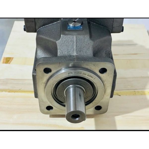
A4VSO125DRG/22R-PPB13N00 A4VSO40LR2G/10L-PPB13N00 A4VSO71LR2/10R-VPB25N00 German Rexroth original hydraulic pump mechanical engineering imported genuine produc
| Item | Specification |
| Product Name | A4VSO Hydraulic Pump |
| Model | A4VSO40 Hydraulic Pump |
| Brand Name | Rexroth |
| Pump Type | Piston Pump |
| Warranty | 1 Year |
| Place of Origin | Fujian, China |
| Connection Size | 1/4 inch |
| Max. Horsepower | 2 HP |
| Number of Stages | 1 Stage |
| Operating Pressure | 100 bar |
| Pressure | Other |
| Structure | Other |
| Material | Carbon Steel |
| Application | Construction Machinery |
| MOQ | 1 Piece |
| After-sales Service Provided | Line Support |
| Package | Wooden Case |
| Color | Customer's Request |

| A4VSO71EO1/30R-VPB13N00 |
| A4VSO71EO1/30R-PPB13N00 |
| A4VSO71LR2/30R-VPB25N00 |
| A4VSO71LR2/30R-VZB13N00 |
| A4VSO71LR2/30R-PZB13N00 |
| A4VSO71LR2/30R-VPB13N00 |
| A4VSO71LR2/30R-PPB13N00 |
| A4VSO125DFR/30R-PZB13N00 |
| A4VSO71DRG/30R-PZB13N00 |
| A4VSO71DRG/30R-VPB13N00 |
| A4VSO71DRG/30R-PPB13N00 |
| A4VSO71DFR/30R-VPB25N00 |
| A4VSO71DFR/30R-VZB13N00 |
| A4VSO71DFR/30R-PZB13N00 |
| A4VSO71DFR/30R-VPB13N00 |
| A4VSO71DR/30R-VZB13N00 |
| A4VSO71DFR/30R-PPB13N0 |
| A4VSO71LR2G/30R-VPB25N00 |
| A4VSO71LR2G/30R-PZB13N00 |
| A4VSO71LR2G/30R-VPB13N00 |
| A4VSO71LR2G/30R-PPB13N00 |
| A4VSO71DR/30R-VPB25N00 |
| A4VSO71LR2G/30R-VZB13N00 |
| A4VSO500DR/22L-PPB13N00 |
| A4VSO71DR/30R-VPB13N00 |
| A4VSO71DR/30R-PPB13N00 |
| A4VSO500EO2/22L-PPB13N00 |
| A4VSO500EO1/22L-PPB13N00 |
| A4VSO500LR2/22L-PPB13N00 |
| A4VSO500DRG/22L-PPB13N00 |
| A4VSO500DFR/22L-PPB13N00 |
FAQ;
1. Cross-Equipment Collaboration & System Matching
Q1: How to match this pump with a variable-frequency drive (VFD) for energy-saving operation, and what parameter settings are critical?
A4: VFD integration optimizes energy use by adjusting motor speed to match flow demand—key steps and settings: ① VFD Selection: Choose a VFD with 110% of the motor’s rated power (e.g., 41 kW VFD for a 37 kW motor) and compatible with the motor’s voltage (380V/400V); ② Wiring Requirements: Use shielded cables for VFD-to-motor connections to reduce electrical interference with the pump’s control system; separate VFD cables from hydraulic sensor cables by ≥30cm; ③ Critical VFD Parameters: 1) Base Frequency: Set to 50Hz (matches motor’s nominal speed of 1500 rpm); 2) Minimum Frequency: 15Hz (avoids motor stalling, corresponds to 450 rpm—above the pump’s minimum stable speed of 600 rpm, adjust if needed); 3) Acceleration/Deceleration Time: Set to 5 seconds (prevents pressure shocks from sudden speed changes); 4) V/F Curve: Select “quadratic” curve to match the pump’s power characteristics (P ∝ Q×p ∝ n×p, where n=speed); ④ Control Linkage: Connect the pump’s pressure sensor (4-20mA) to the VFD’s analog input—program the VFD to increase speed when pressure >300 bar (demands more flow) and decrease speed when pressure <200 bar (reduces flow). This integration reduces energy consumption by 35-45% in variable-load applications (e.g., concrete pumps).
Q2: What precautions apply when integrating the pump with a hydraulic winch system (e.g., offshore cranes)?
A5: Winch systems require precise speed control and safety redundancy—critical integration precautions: ① Flow Control Coordination: Install a proportional flow control valve (Rexroth 2FRE 10-4X/10LB) between the pump and winch to fine-tune winch speed independently of the pump’s LR2 control; ② Safety Interlocks: Connect the winch’s emergency brake to the pump’s control system—if pump pressure drops below 100 bar, the brake engages automatically to prevent load free-fall; ③ Pressure Compensation: Set the pump’s LR2 power limit to 110% of the winch’s maximum load power (e.g., 41 kW for a 37 kW winch) to handle sudden load spikes (e.g., wave-induced load surges in offshore use); ④ Heat Dissipation: Winch systems often operate at low speed (high torque), increasing pump heat—install an oil cooler with 2x the standard capacity (e.g., 10 kW instead of 5 kW); ⑤ Line Routing: Route pressure lines to the winch with minimal bends (≤2 bends per meter) to reduce pressure drop (≤5 bar) and avoid winch speed fluctuations. Improper integration can lead to winch speed instability (±10%) or brake failure.