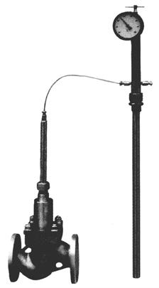
ZZWP Self-operated Temperature Regulating Valve
The ZZWP type self-operated temperature regulating valve is mainly composed of a temperature controller and a single-seat regulating valve. It is an energy-saving product that realizes automatic regulation relying on the temperature change of the controlled medium itself without external energy sources. This product is equipped with a temperature regulation and overload protection mechanism, featuring a compact structure and reliable operation. It is suitable for automatic temperature control in various heat exchangers using non-corrosive gases, steam, hot water, oil, etc., as media. It is widely applied in automatic temperature regulation of various water supply, heating, refrigeration, heat exchange, sterilization, disinfection and other equipment in petroleum chemical industry, electric power, metallurgy, food, light industry and textile, machinery manufacturing, residential building complexes, hotels, restaurants, etc.
1. Basic Technical Parameters |
Nominal diameter DN(mm) | 20 | 25 | 32 | 40 | 50 | 65 | 80 | 100 | 125 | 150 |
rated flow coefficient Kv | 1.2 | 2 | 3.2 | 5 | 8 | 12.5 | 20 | 32 | 50 | 80 | 125 | 160 | 280 |
nominal pressure MPa | 1.64.0 |
working stroke (mm) | 6 | 8 | 10 | 16 | 18 | 18 | 18 | 20 |
allowable pressure difference MPa | ≤1.6 | 1.5 | 1.5 | 0.5 |
maximum operating temperature | ≤200℃ | 140℃ |
balancing element | Bellows | diaphragm |
actuator model | ZZW-1 | ZZW-2 |
valve body material | cast steel and cast stainless steel |
valve core and valve seat material | 1Cr18Ni90Cr18Ni12Mo2Ti |
flange standard | JB/T79.1-94 |
temperature setting range (℃) | 0~4020~5040~7060~9080~120 |
control accuracy | ≤±3% |
allowable leakage | 10⁻⁴ × valve rated capacity |
ambient temperature | should be lower than the lower limit of the set temperature |
allowable overload | 20% above the upper limit of the temperature setting range |
temperature bulb size | φ20×350 | φ25×450 |
temperature bulb connection thread | M27×2 | M36×2 |
capillary length | 3 meters (for special specifications, 5, 10, 15 meters are available as specified when placing an order) |
temperature bulb material | brass H62, stainless steel 1Cr18Ni9Ti |
time constant (S) | ≤100 |
Operating Principle |
The self-operated temperature regulating valve utilizes the characteristic that the saturated vapor pressure of the temperature-sensing liquid filled in the closed system composed of a temperature bulb, capillary tube, and bellows changes with temperature. This causes the displacement of the bellows to change accordingly, driving the valve core to a corresponding opening degree, thereby achieving the purpose of regulating the flow of hot and cold media. The saturated vapor pressure of the temperature-sensing liquid is proportional to the temperature of the bulb. When the temperature increases, the vapor pressure rises, and the force acting on the bellows increases. When this force is greater than the force of the temperature-setting spring, the bellows, together with the push rod and valve core, moves downward, reducing the valve opening, decreasing the flow of the heating medium, and reducing the temperature difference in the heat exchanger until the saturated vapor pressure in the closed system balances with the temperature setting and the spring force. Conversely, when the temperature decreases, the vapor pressure decreases, and when the force on the bellows is less than the set spring force, the valve opening increases, the flow of the heating medium increases, and the temperature quickly returns to the set value. The temperature adjustment nut is used to adjust the set temperature within a certain temperature range. The small spring is used for overload protection, that is, after the valve core is closed, if the temperature exceeds the set value (i.e., the saturated vapor pressure is too high), the bellows can continue to move downward without being damaged. It can automatically resume normal operation after unloading. The magnitude of the overload can be adjusted by the small spring, which has been set at the factory, so users do not need to adjust it themselves. |
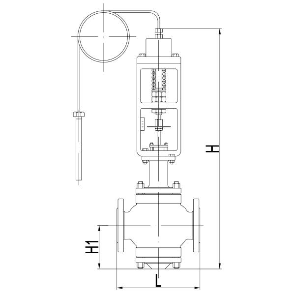
Overall dimensions

Nominal diameter (DN) | 20 | 25 | 32 | 40 | 50 | 65 | 80 | 100 | 125 | 150 |
L | 180 | 185 | 200 | 220 | 250 | 275 | 300 | 350 | 410 | 450 |
H1 | 60 | 117 | 120 | 139 | 144 | 188 | 208 | 220 | 235 | 250 |
H | 632 | 650 | 700 | 775 | 790 | 850 | 950 | 1050 | 1160 | 1250 |
Installation, Operation, and Maintenance |
- Use the valve under specified conditions, install it vertically, and ensure the medium flow direction is consistent with the arrow on the valve body.
- Select an installation location with minimal impact and vibration.
- Immerse the temperature bulb horizontally or obliquely in the medium. The bending radius of the capillary tube must not be less than 75mm, and it should be kept in a natural state. Sharp-angle bending is strictly prohibited to avoid breaking the capillary tube.
- The valve is factory-set according to user requirements and can be installed and operated immediately upon delivery.
- If there is a significant deviation between the controlled medium temperature and the set temperature, manually adjust the temperature-regulating nut. Turn it counterclockwise when the medium temperature is lower than the set value.
- Close the shut-off valve before the temperature-regulating valve when heating is stopped or the medium is not in use.
- A bypass is generally installed for the temperature-regulating valve to facilitate emergency use and maintenance.
|
Ordering Information |
- Product model
- Nominal pressure
- Temperature regulating range
- Nominal diameter and rated flow coefficient
- Medium name and temperature
- Valve body material
- Capillary material and length
- Other special requirements (such as accessories, supply of special flanges, etc.)
|