HLC Small-Bore Cage Single-Seated Control Valve is a high-performance single-seated control valve suitable for high-pressure difference applications where the liquid pressure difference exceeds 3 MPa. The robust valve plug guidance and cage prevent liquid flashing and cavitation. The valve body features an S-streamline channel, ensuring minimal pressure drop loss, large flow capacity, and a wide adjustable range.
The control valve is equipped with a multi-spring diaphragm actuator, which offers a compact structure and high output force.
Trim
| Plug Type | Single-seated cage-type piston plug |
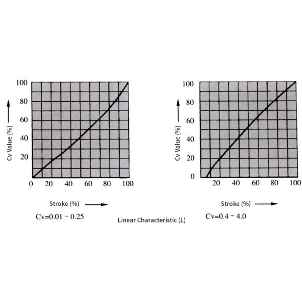
| Flow Characteristics | Equal percentage (%) and linear (L) (for metal seats), refer to Figures 1 and 2 |
| Cage Type | Split cage |
| Materials | 17-4PH, 0Cr17Ni12Mo2 |
Actuator
| Type | HA Multi-spring Diaphragm Actuator |
| Diaphragm Material | EPDM with Nylon Insert |
| Spring Range | 0.02~0.10 MPa, 0.08~0.24 MPa |
| Supply Pressure | 0.14 MPa, 0.16 MPa, 0.28 MPa |
| Air Supply Connection | Rc 1/4 |
| Ambient Temperature | -30~+70℃ |
| Valve Action Type | HA Multi-spring Diaphragm Actuator |
| Accessories | Positioner, Handwheel Mechanism, Pneumatic Valve Position Transmitter |
Performance
| Leakage | Complies with ANSI B16.104 Class IV standard, less than 0.01% of rated Cv |
| Hysteresis | 1% (with positioner), 3% (without positioner) |
| Linearity | ±1% (with positioner), ±5% (without positioner) Remarks: Standard V-type PTFE packing is adopted |
| Adjustable Range | 50∶1 (Cv ≥ 0.25) or 30∶1 (Cv ≤ 0.16) |
Cv Values and Stroke
Table 1
| Rated Cv Value | 0.01 | 0.04 | 0.1 | 0.16 | 0.25 | 0.4 | 0.63 | 1.0 | 2.5 | 4.0 |
| Flow Characteristics | Metal Seat | Equal Percentage | | | | | ○ | ○ | ○ | ○ | ○ | ○ |
| Linear | ○ | ○ | ○ | ○ | ○ | ○ | ○ | ○ | ○ | ○ |
| Rated Stroke (mm) | 14.3 |
| Nominal Diameter | 20,25 |
Remarks: The symbol ○ indicates the specification range of the valve.
Flow Characteristics
Equal Percentage Characteristic (%)Figure 1 Flow Characteristics Curve


Figure 2 Flow Characteristics Curve
Allowable Pressure Difference
Table 2
| Actuator | Supply Pressure(Mpa) | Spring Rang(Mpa) | Positioner | Allowable Pressure Differential(Mpa) |
| Rated Cv Value |
| ≤0.25 | 0.40 | 0.63 | 1.0 | 1.6 | 2.5 | 4.0 |
HA2D (HA2R) | 0.14 | 0.02~0.10 | With or Without | 4.0 10 | 4.0 6.2 | 4.0 6.2 | 3.26 | 3.26 | 2.0 | 2.0 |
| 0.16 (0.28) | 0.02~0.10 (0.08~0.24) | With | - | 4.0 10 | 4.0 10 | 4.0 10 | 4.0 10 | 4.0 10 | 4.0 10 |
Remarks:
1.The maximum allowable pressure difference shall not exceed the maximum values specified in ANSI B16.34 or JIS B2201 standards.
2.The upper figures in the same cell indicate the allowable pressure difference when the valve is fully open, and the lower figures indicate
the allowable pressure difference when the valve is fully closed.
3.The values in parentheses are for reverse acting actuators.
Flange Distance
Table 3 Unit:mm
| Nominal Diameter | A |
| ANSI 125 FF ANSI 150 RF JIS 10K FF RF PN 1.6 MPa | JIS 16K RF | ANSI 300 JIS 20,30K RF PN 4.0MPa | ANSI 600 JIS 40K RF PN6.4 MPa | ANSI 150 RJ | ANSI 300 RJ | ANSI 600 RJ | JIS 20K LG | JIS 30K LG | | ANSI 600 SW,BW |
| 20 | 184 | 190 | 194 | 206 | | 206 | 206 | 198 | 208 | 203 | 206 |
| 25 | 184 | 193 | 197 | 210 | 197 | 210 | 210 | 198 | 212 | 206 | 210 |
Ordering Instructions
1.Model number
2.Nominal diameter × seat diameter
3.Nominal pressure and flange connection type
4.Body and trim materials, surface hardening treatment requirements
5.Bonnet type
6.Flow characteristics
7.Actuator model, air supply pressure
8.Valve action type
9.Accessories (positioner, handwheel, pressure regulator, etc.)
10.Special requirements (oil-free, copper-free, etc.)
11.Medium name
12.Normal flow rate and required maximum flow rate
13.Medium pressure, inlet and outlet pressures at maximum and minimum flow rates
14.Medium temperature and specific gravity
15.Medium viscosity, and whether it contains suspensions