Deck-Mounted Cast Steel Mooring Chock | DIN 81915:1998-08 Type C, SWL 10–320 kN
Product Overview
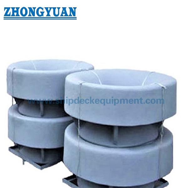
The DIN 81915 Type C deck-mounted mooring chock is a closed cast steel rope guide used to lead mooring or towing lines between the vessel's inboard deck arrangement and the ship side. Its closed opening controls the rope path, while the rounded rope-contact surfaces reduce sharp local contact and help limit abrasion during line handling.
Type C is installed on a welded deck seat or directly at the specified deck foundation, depending on the vessel drawing. The supplied range covers Type C1 to C32 with stated SWL values from 10 to 320 kN. Selection should consider the fitting SWL, rope type and diameter, rope MBL, lead direction, deck reinforcement, weld details, material grade, coating system, inspection scope, and classification requirement.
Quick Specifications
Main Technical Parameters
| Nominal size |
SWL KN |
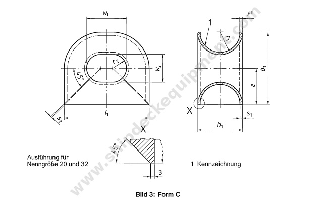
b1 | b2 | d | e | f | h1 | h2 | h3 | l1 | l2 | r1 | r2 | s1 | s2 | w1 | w2 | Weight (GGG) kg |
Weight (GS) kg |
| 1 | 10 | 250 | 175 | 30 | 125 | 15 | 160 | 65 | 20 | 285 | 115 | R80 | R45 | 10 | 5 | 125 | 90 | 18 | 19.5 |
| 2 | 20 | 315 | 225 | 35 | 158 | 18 | 200 | 70 | 25 | 360 | 125 | R100 | R57.5 | 12 | 6 | 160 | 115 | 27 | 29 |
| 3 | 30 | 390 | 275 | 40 | 195 | 21 | 250 | 75 | 32 | 450 | 140 | R125 | R70 | 14 | 7 | 200 | 140 | 44 | 48 |
| 5 | 50 | 480 | 340 | 45 | 240 | 24 | 300 | 80 | 38 | 550 | 160 | R150 | R90 | 16 | 8 | 250 | 180 | 78 | 85 |
| 8 | 80 | 585 | 415 | 50 | 293 | 27 | 360 | 90 | 45 | 680 | 180 | R180 | R112.5 | 18 | 9 | 320 | 225 | 127 | 136 |
| 12 | 120 | 710 | 500 | - | 355 | 30 | 440 | 110 | 55 | 840 | - | R220 | R135 | 20 | 10 | 400 | 270 | 199 | 211 |
| 20 | 200 | 840 | 595 | - | 420 | 33 | 520 | 130 | 65 | 1020 | - | R260 | R160 | 22 | 11 | 500 | 320 | 302 | 325 |
| 32 | 320 | 1100 | 800 | - | 550 | - | 700 | 150 | 80 | 1300 | - | R350 | R200 | 35 | 20 | 600 | 400 | 770 | 840 |
Selection & Inquiry Guide
Step 1: Confirm DIN 81915 Type C and select C1 to C32 according to the required chock SWL and the vessel's approved mooring or towing arrangement.
Step 2: Provide rope type, rope diameter, rope MBL, expected line direction, lead angle, and whether the duty is mooring, towing-line guidance, or replacement service.
Step 3: Confirm deck installation position, available seat space, foundation plate, weld detail, surrounding deck reinforcement, and any interference with nearby fittings.
Step 4: Confirm material grade and temperature requirement: C-Mn cast steel, cast stainless steel, or special low-temperature steel for ice-service projects.
Step 5: Confirm surface treatment, rope-contact finishing, material traceability, NDT or load-test requirement, and the classification society inspection scope before quotation.
Step 6: Provide quantity, vessel type, drawing or reference photo, delivery destination, required delivery date, packing requirement, and replacement dimensions if applicable.
Structure
Closed cast steel chock body | Rounded rope-contact opening | Deck-mounted base / seat interface | Welded connection area | Reinforced transition geometry | Blasted and primed surface or specified finish
Casting, Installation & Engineering Advantages
Custom Attributes
How It Works
Mooring or towing line approaches the chock → Line passes through the closed rounded opening → Contact surfaces control the lead direction and reduce sharp rubbing → Local fitting load is transferred through the chock base and welds into the reinforced deck structure
Applications
Cargo vessels | Tankers | Tugs | Workboats | Service vessels | Ship bow and stern mooring stations | Deck-mounted towing-line guides | Newbuilding projects | Repair and replacement projects
Certifications & Advantages
Material certificates, maker certificates, class inspection, NDT witnessing, and load-test documentation can be arranged according to project requirement, agreed inspection scope, and class approval procedure.
Certification: CCS, NK, BV, ABS, DNV, LR, KR, IRS, RS, RINA, CRS, Makers Test Certificate.
Drawing & Photos


FAQ
Q1: Is the stated SWL the same as the rope MBL?
A1: No. The table identifies the chock fitting SWL, while rope MBL is the minimum breaking load of the line. The vessel designer should confirm the relationship between rope MBL, design load, fitting SWL, load direction, and the applicable safety or design factors.
Q2: What is the practical difference between DIN 81915 Type C and Type A?
A2: Type C is the deck-mounted closed chock configuration. Type A is generally supplied as the bulwark-mounted configuration. The correct type must match the vessel drawing, rope lead height, installation position, and available structure.
Q3: What information is required for an accurate quotation?
A3: Confirm standard and type, required SWL, rope data, material grade, surface treatment, quantity, installation drawing, deck seat and reinforcement arrangement, class requirement, inspection scope, delivery destination, and required delivery date.