Product Description
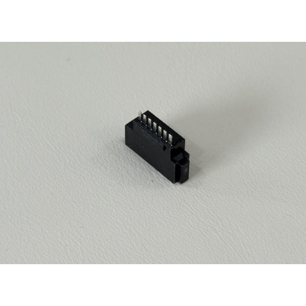
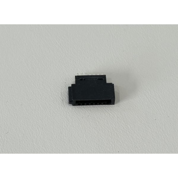
This 7 pin SATA female connector is designed for reliable electrical signal and low-voltage power transmission in compact cable harnesses. The wire solder termination allows flexible cable routing and easy integration into custom assemblies for storage, industrial and embedded systems. Gold plated contacts over nickel provide low contact resistance, excellent corrosion resistance and stable performance over long service life.
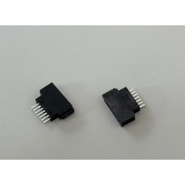
The high-temperature, flame-retardant thermoplastic housing and copper-alloy terminals ensure mechanical strength during repeated mating and handling. The connector supports customization for wire gauge, cable length, labeling and overmolding, making it suitable for OEM/ODM projects that require tailored PCB-to-cable interconnect solutions.

| Connector type | 7-pin PCB female socket connector |
| Application | Signal and low-power transmission between PCB and cable/board |
| Mounting style | Right-angle SMT / solder-tail to PCB |
| Pitch | 1.27 mm (typical SATA-style interface) |
| Positions | 7 pins (other pin counts customizable) |
| Contact material | Copper alloy terminals, high conductivity |
| Contact plating | Nickel underplate, gold on contact area, tin on solder tail |
| Housing material | High-temperature, glass-filled thermoplastic, UL94-V0 flame rating |
| Rated current | 1.5 A per pin (max, signal / low-power lines) |
| Rated voltage | Up to 250 V AC (creepage/clearance dependent) |
| Contact resistance | ≤ 30 mΩ (initial) |
| Insulation resistance | ≥ 1000 MΩ at 500 V DC |
| Dielectric withstand | 500 VAC / 1 minute, no breakdown |
| Mating cycles | Up to 1500 mating/unmating cycles under rated conditions |
| Operating temperature | -20 °C to +80 °C (typical for this series) |
| Compliance | RoHS / HF / REACH-compatible, halogen-free options available |
| Customization | Pin count, plating thickness, housing color, packaging and matched cable assemblies available |
Applications
PCB-to-cable or PCB-to-board interfaces in industrial control units, PLCs and inverters
Internal server and storage modules, signal lines for HDD/SSD and backplane connections
Automotive electronics, such as battery management, on-board chargers, ADAS controllers and infotainment units
Customized harness assemblies for power plus signal routing in communication equipment and smart devices
Compact embedded systems, test fixtures and measurement instruments requiring repeated mating cycles
Precautions
-
Mating compatibility
Use only with matching 7-pin plug or header designed for the same pitch and keying to avoid bent terminals or intermittent contact. -
Current and voltage limits
Do not exceed the specified current per pin or overall temperature rise; parallel multiple pins for higher current if required in the design. -
Soldering recommendations
Follow recommended reflow or wave solder profiles for high-temperature thermoplastic housings. Avoid excessive peak temperatures or dwell time to prevent housing deformation or terminal loosening. -
Mechanical handling
Insert and withdraw the mating connector in a straight line; avoid twisting or side-loading forces on the housing. Ensure proper PCB support to reduce stress on solder joints. -
Environmental conditions
Operate within the specified temperature and humidity range; for applications with condensation, vibration or dust, consider conformal coating or additional sealing measures. -
Quality and reliability
Periodically verify contact resistance and insulation resistance in long-life equipment or safety-critical systems, especially where frequent mating cycles or harsh environments are expected.