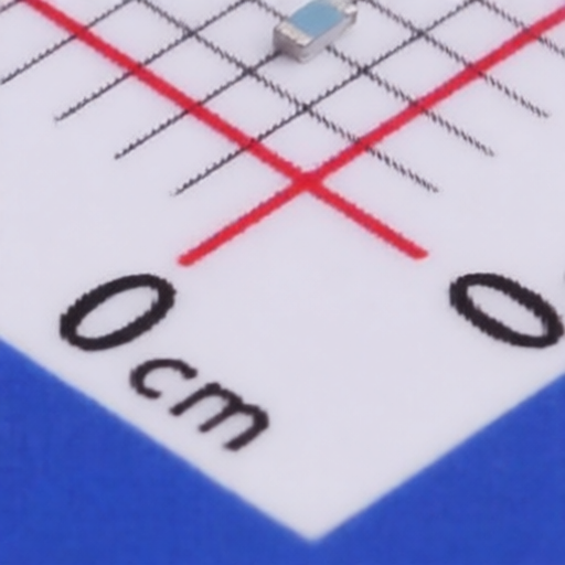
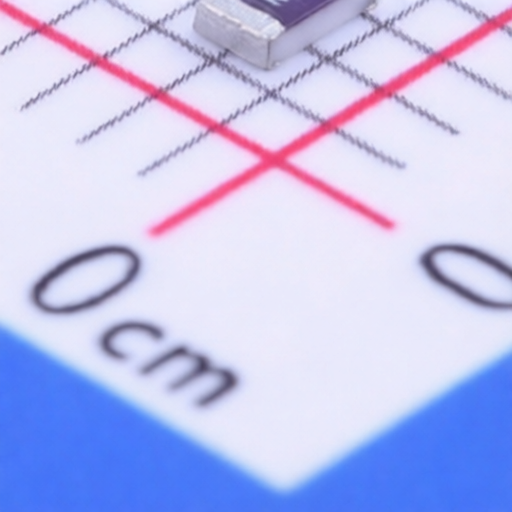
The TE Connectivity CRGP Series SMD Pulse withstand thick film Chip Resistor is designed for high-volume, automated placement in a wide range of applications. Its small size and light weight make it suitable for both wave and reflow soldering techniques. Available in seven different package sizes and supplied on tape and reel, these resistors offer pulse rating capabilities and are ideal for applications requiring reliable performance under transient load conditions.
| Type | Power Rating @ 70C | Max. Working Voltage | Max. Overload Voltage | Dielectric Withstand | Temperature Range | Resistance Range | Tolerance | Dimensions (L x W x H) mm |
| CRGP0402 | 0.125W | 50V | 100V | 100V | -55C ~ +155C | 1R0 10M | 1%, 5% | 1.100.10 x 0.500.05 x 0.350.05 |
| CRGP0603 | 0.25W | 50V | 100V | 300V | -55C ~ +155C | 1R0 10M | 1%, 5% | 1.600.10 x 0.800.10 x 0.450.10 |
| CRGP0805 | 0.33W | 150V | 300V | 500V | -55C ~ +155C | 1R0 10M | 1%, 5% | 2.000.15 x 1.25+0.15/-0.10 x 0.550.10 |
| CRGP1206 | 0.5W | 200V | 400V | 500V | -55C ~ +155C | 1R0 10M | 1%, 5% | 3.100.15 x 1.55+0.15/-0.10 x 0.550.10 |
| CRGP1210 | 0.75W | 200V | 500V | 500V | -55C ~ +155C | 1R0 10M | 1%, 5% | 3.100.10 x 2.600.20 x 0.550.10 |
| CRGP2010 | 1.25W | 400V | 800V | 500V | -55C ~ +155C | 1R0 10M | 1%, 5% | 5.000.10 x 2.500.20 x 0.550.10 |
| CRGP2512 | 2W | 500V | 1000V | 500V | -55C ~ +155C | 1R0 10M | 1%, 5% | 6.350.10 x 3.200.20 x 0.550.10 |
| Characteristic | Limits | Test Methods (JIS C 5201-1) |
| Temperature Coefficient | 100PPM/C (Standard) *0402: 400 PPM/ (1-10), 200 PPM/ (11-100), 100 PPM/ (>100) | Natural resistance change per temp. degree centigrade (Sub-clause 4.8) |
| Short term overload | 5%: (2.0% 0.1) Max. 1%: (1.0% 0.1) Max. | Permanent resistance change after the application of a potential of 2.5 times RCWV for 5 seconds (Sub-clause 4.13) |
| Terminal Bending | (1.0% 0.05) Max. | Twist of Test Board : Y/X = 5/90 mm for 10 seconds (Sub-clause 4.33) |
| Insulation Resistance | 1,000M or more | Apply 500V DC between protective coating and termination for 1 min, then measure (Sub-clause 5.6) |
| Dielectric Withstand Voltage | No evidence of flashover, mechanical damage, arcing or insulation breakdown. | Apply 500V AC between protective coating and termination for 1 minute (Sub-clause 4.7) |
| Soldering Heat | (1.0% +0.05) Max. | Dip the resistor into a solder bath having a temperature of 260C3C and hold it for 101 seconds (Sub-clause 4.18) |
| Solderability | 95% coverage Min. | Test temperature of solder : 245 3 Dwell time in solder : 2 ~ 3 seconds (Sub-clause 4.17) |
| Temperature Cycling | 5%: (3%0.1) Max. 1%: (0.5%0.1) Max. | Resistance change after continuous 5 cycles (Sub-clause 4.19) |
| Humidity | (3.0% + 0.1) Max. | Temporary resistance change after 240 hours exposure in a humidity test chamber controlled at 402C and 90-95% relative humidity (Sub-clause 4.24) |
| Load Life In Humidity | 5%: (3.0% 0.1) Max. 1%: (1.0% 0.1) Max. | Resistance change after 1,000 hours at RCWV in a humidity chamber controlled at 40 2 and 90 to 95 % relative humidity (Sub-clause 4.24.2.1) |
| Load Life | 5%: (3.0% 0.1) Max. 1%: (1.0% 0.1) Max. | Permanent resistance change after 1,000 hours operating at RCWV, at 70 2 ambient (Sub-clause 4.25.1) |