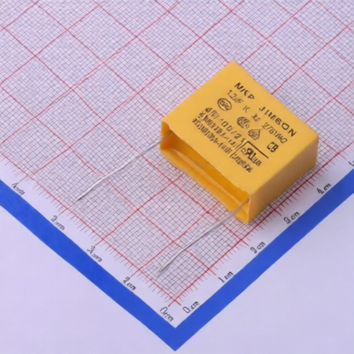
This specification applies to high voltage ceramic capacitors used in high voltage electric equipment. These capacitors are designed for applications requiring high reliability and are manufactured with a unique N4700 -grade ceramic dielectric material, offering high voltage capabilities from 2KV to 50KV. They are particularly suited for high-end medical electronic equipment, airport security, non-destructive testing, and electrostatic dust removal equipment.
| Part Number | DC Rated Voltage (kV) | Capacitance (pF) | Capacitance Tolerance | Temperature Characteristic | Dimensions (mm) D x T x F | Lead Style | Packing Type |
| HVC-20KV-DL13-F10-221K | 20KV | 220 pF | K (10%) | N4700 (-4700ppm/C) | DL13 (D=11mm, T=13mm, F=10mm) | Straight long | Bulk |
Operating Voltage: Maintain applied voltage (DC, AC, or ripple) within the rated voltage range. Account for transient voltages during circuit start-up or shut-down.
Operating Temperature and Self-Generated Heat: Keep surface temperature below the rated operating temperature. Consider self-generated heat due to dielectric loss, especially in high-frequency or pulse current applications. Applied voltage should limit self-generated heat to within 5C at 25C ambient temperature.
Operating and Storage Environment: Avoid corrosive atmospheres (chloride gas, sulfide gas, acid, alkali, salt) and moisture. Ensure at least 3mm of insulating media around the capacitor. Storage temperature: -10 to 40C; Relative humidity: 15 to 85%. Use within 6 months of delivery.
Vibration and Impact: Do not expose to excessive shock or vibration.
Soldering: Adhere to solder heat resistance specifications. Soldering iron tip: 400C max. Wattage: 50W max. Time: 3.5s max. Failure to comply may result in short circuits or product damage.
Limitation of Applications: Contact HVC before using in applications requiring exceptionally high reliability, such as aircraft, aerospace, medical, transportation, and power plant control equipment.
Cleaning: For ultrasonic cleaning, use a rinse bath capacity of 20 watts/liter or less for a maximum of 5 minutes. Do not vibrate the PCB/PWB directly.
Capacitance Change: Class 1 capacitors may show slight capacitance changes with temperature or voltage. Class 2 and 3 capacitors (e.g., B, E, F temperature characteristics) exhibit aging and significant changes with temperature and voltage, making them unsuitable for strict time constant circuits.
| Category | Item | Specification | Testing Method |
| Visual Examination | Appearance dimensions | See 3, 4 | Visually examined or Venire Calipers |
| Marking | To be easily legible | Visually examined | |
| Electrical Performance Tests | Dielectric Strength (Between Lead wires) | No failure | DC voltage of 150% of rated voltage applied for 60 s in insulating liquid or gas (Charge/discharge current: 50mA max.) |
| Body Insulation | No failure | DC voltage of 15kV applied for 10 s between lead wires and small metals (Charge/discharge current: 50mA max.) | |
| Insulation Resistance (I.R.) | W min. (200,000 M) | DC 1kV measured within 605 s of charging | |
| Capacitance | Within specified tolerance | Measured at 20C, 10.2kHz, AC5V(r.m.s.) max. | |
| Dissipation Factor (D.F.) | 0.2% max. | Same condition as capacitance | |
| Temperature Characteristic | Capacitance change from value at 20C shall not exceed limits specified in table. | Measurements at -4700ppm/C, 202C, 852C. | |
| Mechanical Performance Tests | Strength of Lead Pull | Lead wire shall not cut off. Capacitor shall not be broken. | Tensile weight of 10N applied radially to lead wire for 101 s. |
| Bending | Each lead wire shall be subjected to 5N weight and 90 bends in opposite directions. | Rate of one bend in 2 to 3 s. | |
| Solderability of Leads | Lead wire shall be soldered with uniformly coated over 3/4 of circumferential direction. | Dipped in 25% methanol solution of rosin, then into molten solder of 2355C for 20.5 s. Dipping depth: 1.5 to 2.0mm from root of lead wires. | |
| Soldering Effect | Appearance: No marked defect. Capacitance Change: Within 10%. Dielectric Strength (Between lead wires): No failure. | Lead wires immersed into melted solder of 35010C up to 1.5 to 2.0mm from main body for 3.50.5 s. Stored for 242 h at room condition post-treatment. |