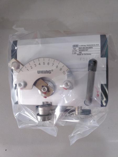
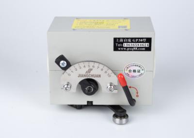
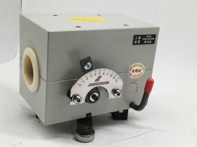
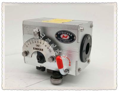
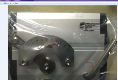
Qipang Rolling ring drive traves unite RG3-20-2MCRFX with roller Rollring Traverse Unit
Shanghai Qi Pang Industrial Co., LTD has been working on the supply of Rolling Ring Drive equipment since 2008. During this time, the company supplied supplies to many cable, textile and construction companies located in most European countries, Southeast Asian countries, the Americas and northern African countries.
| Model type | Linear Pitch mm/r | Thrust N | Weight Kg |
| GP3-15 | 11 | 110 | 0.9 |
| GP3-20 | 16 | 160 | 1.6 |
| GP3-22 | 16 | 160 | 2 |
| GP3-25 | 25 | 260 | 3 |
| GP3-30 | 25 | 260 | 2.7 |
| GP3-40 | 32 | 420 | 11.2 |
| GP3-50 | 40 | 700 | 33 |
| GP3-60 | 48 | 1000 | 42 |
| Model type | Linear Pitch mm/r | Trust N | Weight Kg |
| GP4-15 | 11 | 220 | 1.5 |
| GP4-20 | 16 | 320 | 3 |
| GP4-30 | 25 | 520 | 3.7 |
| GP4-40 | 32 | 840 | 13 |
| GP4-50 | 40 | 1400 | 38 |
| GP4-60 | 48 | 2000 | 45 |
| Model | GP15 | GP20 | GP30 | GP40 | GP50 | GP60 |
| A*B*C ( mm ) | 92*52*66 | 111*68*85 | 135*85*105 | 160*101*129 | 184*119*149 | 220*132*160 |
| D | | 215 | 215 | 240 | 360 | 360 |
| E | | 30-60 | 30-60 | 32-77 | 37-77 | 37-77 |
| F | | 25 | 25 | 32 | 38 | 38 |
| G | 14 | 14 | 14 | 17 | 25 | 25 |
| H | 38 | 40 | 42 | 50 | 60 | 60 |
| I | 16 | 18 | 20 | 22 | 28 | 28 |
| J | 24 | 35 | 55 | 60 | 70 | 70 |
| K | 48 | 60 | 70 | 85 | 96 | 101 |
| M | | 50 | 50 | 65 | 65 | 65 |
| S | 40 | 70 | 70 | 76 | 100 | 100 |
| N | 32 | 40 | 60 | 70 | 80 | 80 |
| 4-M | 4-M6 | 4-M6 | 4-M6 | 4-M12 | 4-M12 | 4-M12 |
| Thrust N | 100 | 135 | 265 | 420 | 700 | 1000 |
| Weight KG | 1.2 | 2.5 | 8.5 | 11.2 | 33 | 42 |
| Moving intercept | 0.1-11 | 0.1-16 | 0.1-25 | 0.5-32 | 1-40 | 1.5-48 |
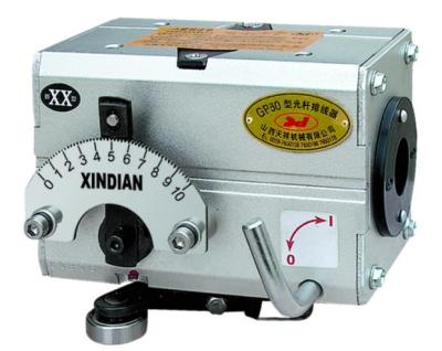
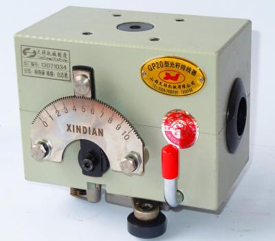
Product display


Installation instruction
It is important to prepare the polished shaft, the guide bar, the end stop lead screw, the endstops, etc. acc
ording to the installation dimensions of relative types and the technical requirementsof equipment, as the figure shows.
Polished Shaft Surface hardness: HRC50- -60; Tolerance on diameter: h6; True runningtolerance: <0. 1mm/m; Length: not larger than 20- 30 times of the diameter of the shaft; Leadingend chamfer: 2x 30°.
Ratio of take-up reel and the shaft in general, the shaft speed should be smaller than thetake- -up reel speed so that the shaft and traverse drive lives could be increased. It isrecommended that the rotation ratio of the shaft over the take-up reel be 1:1-1:5, with lower ratiofor thicker wires and higher ratio for thinner wires, and the scale indication not being less than 1.
Direction of Shaft Rotation the rotation direction of the shaft transmitted by the take- -up reelmay be either positive or negative, however, there is difference regarding the installation positionsof the reversal arm, or otherwise the direction could not be switched. When facing the scale dial,downward rotation is defined as positive. The reversal may be realized only when the trigger rolleris installed backward. The shaft rotation is presetted and installed as in positive direction at thefactory.