51.20kWh 560V High Voltage Battery System with Ten Modular Rack Units
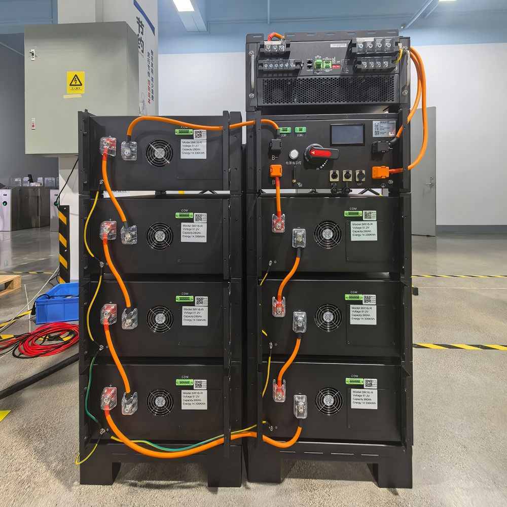
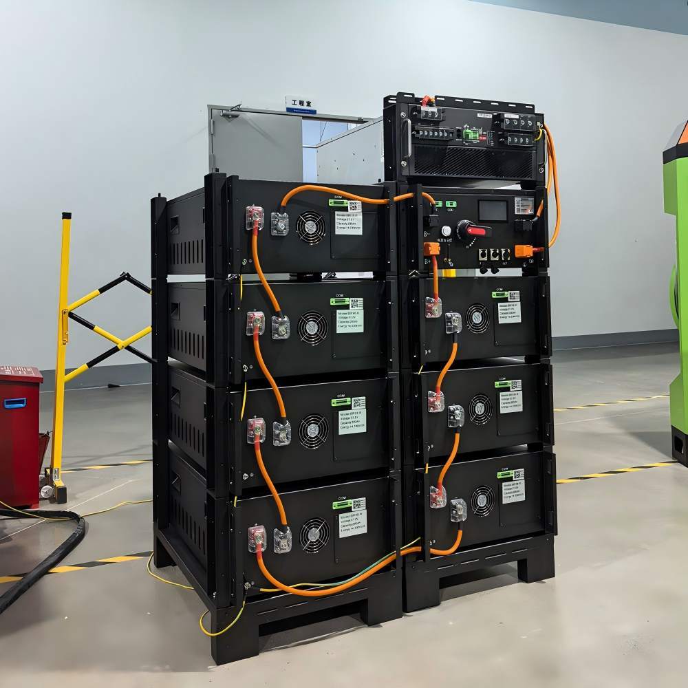
This 51.20kWh high voltage battery system combines ten modular LiFePO4 rack units into a nominal 560V battery bank. It is the highest-capacity configuration within this modular series and requires coordinated planning for energy demand, PCS compatibility, rack loading and installation logistics.
A ten-module battery bank should be treated as an engineered system rather than a group of individual products. The rack arrangement, output protection, cable route and PCS connection should be finalized before delivery.
The project plan should include the following stages:
1. Confirm the required energy reserve and operating schedule.
2. Verify the PCS voltage range and current capability.
3. Approve the rack structure and floor loading.
4. Confirm delivery access and module-handling equipment.
5. Prepare the series-connection and commissioning procedure.
The 51.20kWh nominal capacity can support larger scheduled energy use or backup objectives when combined with a compatible PCS and adequate charging source.
The system design should separate the energy used during normal cycles from the capacity reserved for backup. This helps prevent the full battery from being consumed before a backup event.
Recharge capability must also be considered. A larger battery bank requires sufficient solar, utility or generator energy to restore the capacity used during operation.
The ten modules have a combined net weight of approximately 480kg. The final installed system will weigh more after the rack, cables and protection equipment are included.
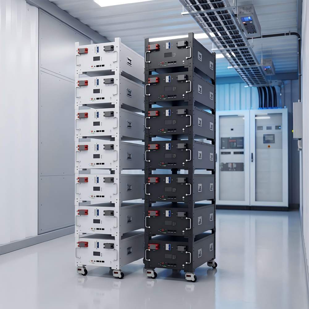
Each module measures 440 × 480 × 150mm. The battery rack must provide space for ten modules while maintaining cable access, ventilation clearance and a safe service path.
The complete module shipment has an approximate gross weight of 540kg before pallets and external packing. Unloading equipment, door dimensions and the internal movement route should be confirmed before dispatch.
Modules should be placed into the rack using a planned sequence that avoids excessive manual handling and leaves connections accessible.
Series links should remain isolated until all module positions, polarity and cable routes have been checked. The complete-stack voltage should be measured before the system output is connected.
The rack should be secured according to the project structure and protected against unintended movement or impact.
The IP20 battery bank requires a dedicated indoor technical area protected from rain, condensation, excessive dust and uncontrolled access.
| High-Voltage Module Bank | 10 × 51.2V 100Ah LiFePO4 Modules |
| Nominal System Energy | 51.20kWh |
| Nominal System Voltage | 560Vdc |
| Battery Operating Range | 464–560Vdc |
| Charge and Discharge Current | 50A Normal / 100A Maximum |
| Communication and Monitoring | CAN / RS485 / LCD |
| Individual Module Dimensions | 440 × 480 × 150mm |
| Combined Module Weight | Approx. 480kg Net / 540kg Gross |
| Environmental Conditions | IP20 / -10°C to 50°C / 0–95% Non-Condensing / ≤1500m |
The system consists of ten individual modules that are installed and connected as one high-voltage battery bank.
Each module weighs 48kg net. A suitable handling method and trained personnel should be used.
Runtime also depends on load power, PCS efficiency, reserve settings and operating conditions.
A dedicated, dry and controlled technical location is recommended for the high-voltage battery system.
Provide unloading capacity, access dimensions, rack position, floor loading and the planned module-handling method.
Preparing a 50kWh-class high-voltage installation?