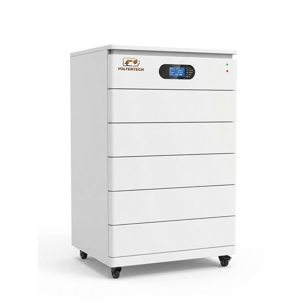
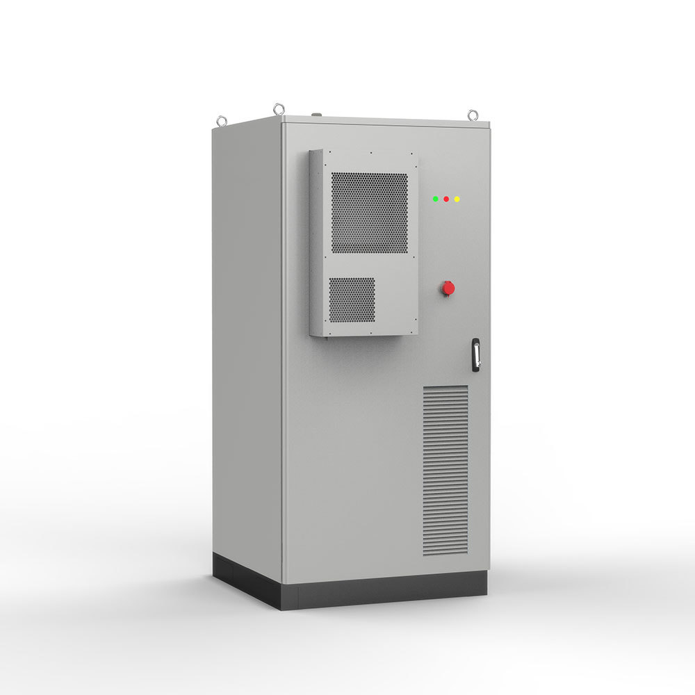
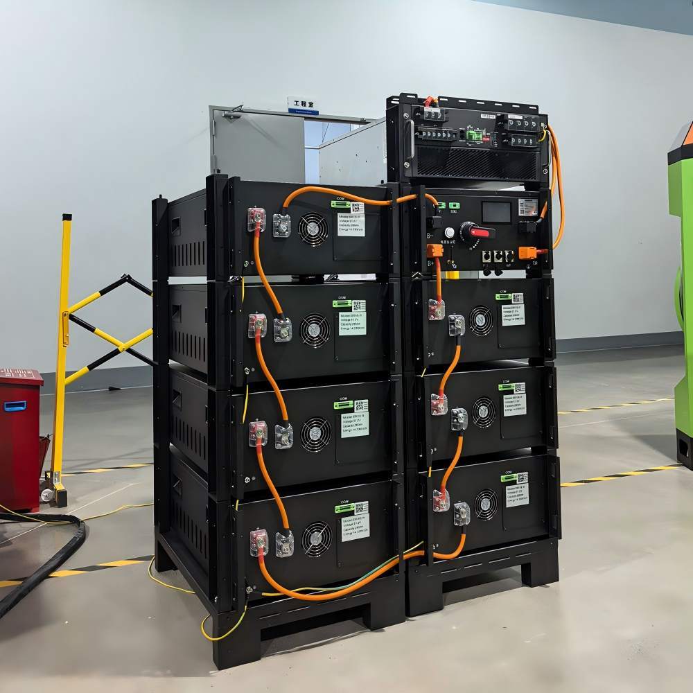
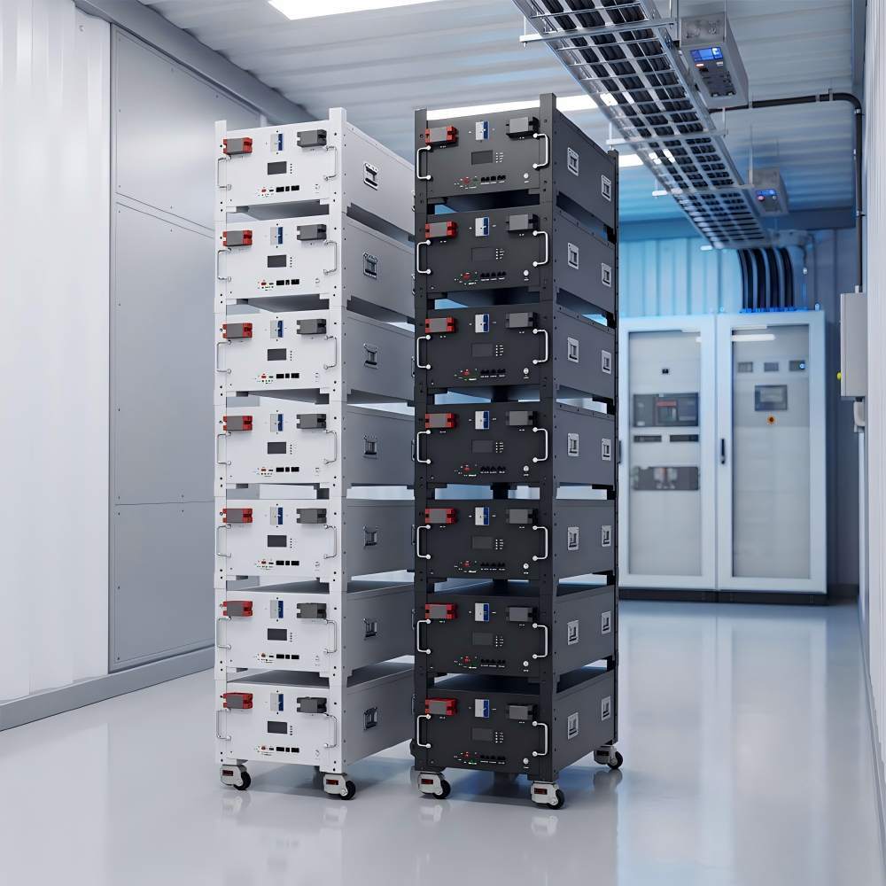
100.35kWh 358.4V High Voltage LiFePO4 Battery System with Rack Design
This 100.35kWh high voltage battery system combines seven rack-mounted LiFePO4 battery units into one 358.4V energy-storage bank. It is designed for solar energy storage, scheduled energy use and selected-load backup projects that require a larger DC energy reserve.
The modular rack format allows the system capacity to be organized across several battery units instead of one oversized enclosure. A compatible high-voltage PCS or inverter, external DC protection and project wiring are selected separately.
The 100.35kWh rating represents nominal stored DC energy. It can be considered for projects that need to store daytime solar production, maintain a planned backup reserve or support selected loads during defined operating periods.
Battery capacity should be selected from actual energy demand rather than PCS power alone. A 100kWh battery bank and a high-power PCS perform different functions: the battery provides stored energy, while the PCS determines charging power and AC output.
Daily Energy Requirement
Calculate how much energy the connected loads are expected to use during each operating cycle.
Backup Reserve
Separate routine energy use from the capacity that must remain available for backup operation.
Recharge Capability
Confirm that the solar array, utility charger or generator can restore the used battery energy within the available charging period.
The complete high voltage battery system uses seven series-connected battery units. Each unit has the same mechanical format, helping simplify rack planning, transportation and future service access.
Each battery unit measures 745 × 440 × 240mm and weighs 118kg net. The supporting rack and floor should be suitable for the combined battery weight together with cables and external protection equipment.
The IP20 enclosure requires a dry indoor installation area. Sufficient space should remain around the battery bank for cable routing, ventilation and routine inspection.
The selected PCS must support the complete 324.8–392Vdc battery operating range. Matching only the nominal 358.4V value is not sufficient because battery voltage changes during charging and discharging.
The maximum continuous charge and discharge current is 150A. Actual project settings may be lower according to the PCS rating, cable design, required power and charging strategy.
Optional CAN or RS485 communication and an optional LCD can be configured according to the selected system requirements.
| System Configuration | Seven Series-Connected LiFePO4 Battery Units |
| Electrical Rating | 358.4V / 280Ah / 100.35kWh |
| Operating Voltage Range | 324.8–392Vdc |
| Floating-Charge Voltage | 392Vdc |
| Continuous Current Limits | 150A Charge / 150A Discharge |
| Maximum Pulse Discharge | 225A |
| Individual Unit Dimensions | 745 × 440 × 240mm |
| Unit Weight | 118kg Net / 138kg Gross Each |
| Operating Conditions | IP20 / -10°C to 50°C / 0–95% Non-Condensing / ≤1500m |
No. A compatible high-voltage PCS or inverter is selected separately.
It is nominal DC energy. PCS efficiency, battery settings and system losses affect available AC energy.
No. The PCS voltage range, current limits and communication requirements must be compatible.
The IP20 battery units require a dry indoor technical location.
Provide the daily energy demand, required backup period, PCS rating and available charging source.
Need to evaluate battery capacity, PCS power and recharge requirements?