560V 100Ah High Voltage LiFePO4 Battery Bank with CAN RS485 Interface
This 560V 100Ah high voltage LiFePO4 battery bank provides 51.20kWh of nominal energy through ten series-connected rack modules. It is designed for compatible PCS systems where a higher DC battery platform, communication integration and structured electrical commissioning are required.
The PCS must support the complete 464–560Vdc operating range. The maximum supported DC voltage must remain suitable for the battery’s upper operating limit, while the minimum value must allow operation at the lower end of the battery range.
The PCS insulation level, DC switching equipment and protective devices must also be selected for the system voltage. Equipment rated for a lower battery platform should not be used without formal approval.
CAN or RS485 communication may exchange supported battery information with a compatible PCS. The required interface should be confirmed from the PCS documentation.
Communication approval should include:
1. PCS brand and exact model.
2. Firmware or software version.
3. CAN or RS485 battery protocol.
4. Cable connector and pin definition.
A matching connector is not sufficient if the data protocol differs.
The normal charge and discharge current is 50A, and the maximum is 100A. The project PCS current should be selected according to required power, cable design and the preferred battery operating strategy.
The maximum current is a battery boundary and does not mean that continuous operation at the maximum value is required.
High-voltage output cables, M8 terminals, breakers, fuses, contactors and disconnects must be suitable for the configured current and complete DC voltage.
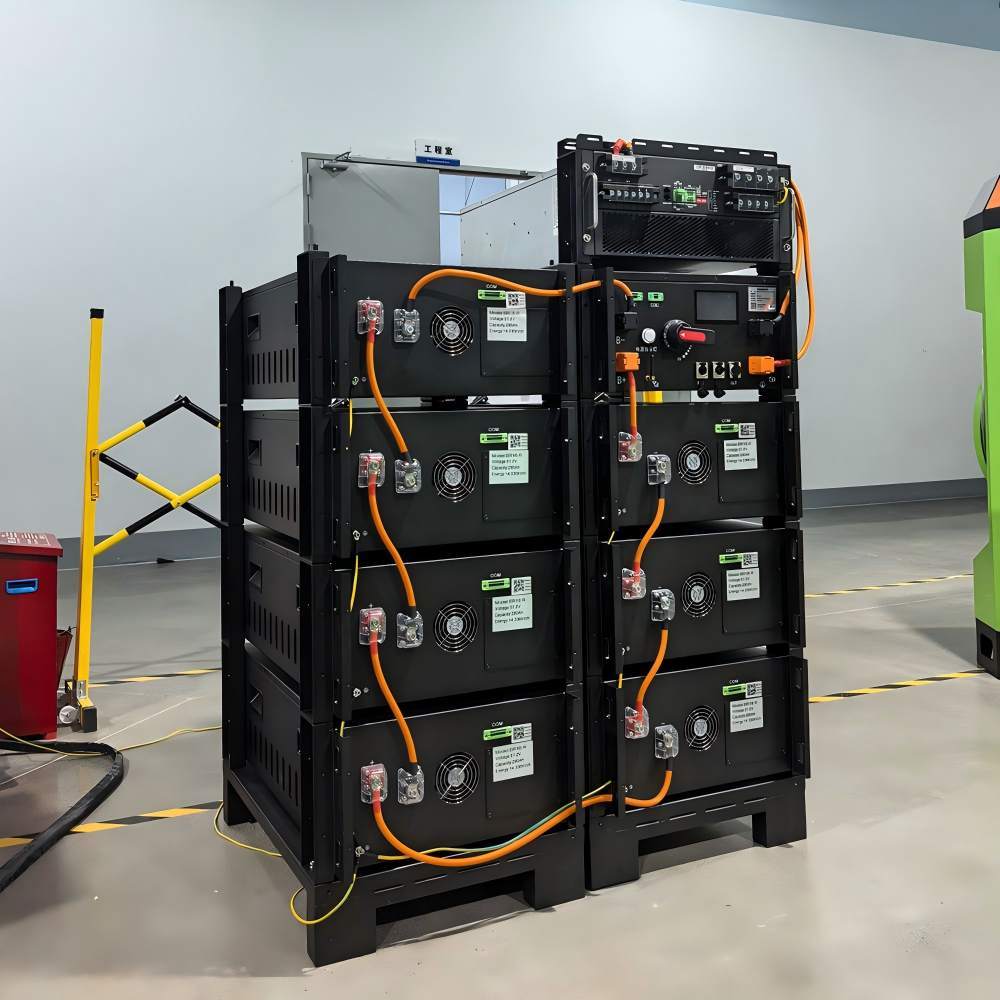
Each module voltage should be recorded before connection. The installation team should then confirm the module order and polarity as the series links are completed.
Before PCS connection, measure the full battery-bank voltage and compare it with the expected value. The system output should remain isolated if the reading is inconsistent.
After electrical checks are complete, verify CAN or RS485 communication, PCS alarms and the available LCD information.
The BMS includes overcharge, overdischarge, overcurrent, short-circuit and overtemperature protection. These functions protect the battery within its designed operating boundaries.
External high-voltage protection remains necessary. The project should include suitable isolation, cable protection, disconnect devices and emergency procedures.
A 560V battery system should only be installed and commissioned by qualified personnel using high-voltage procedures appropriate to the site.
| High-Voltage Energy Bank | 560V / 100Ah / 51.20kWh |
| PCS Operating Voltage Range | 464–560Vdc |
| Normal Battery Current | 50A Charge / Discharge |
| Maximum Battery Current | 100A Charge / Discharge |
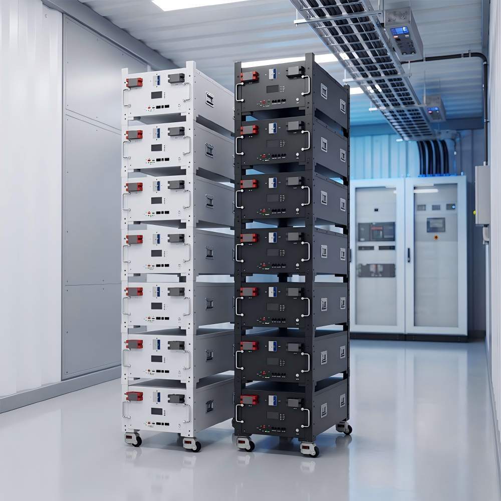
| Series Battery Modules | Ten 51.2V 100Ah Rack Modules |
| Communication Method | CAN / RS485 |
| Battery-Side Display | LCD |
| Protection Coverage | Overcharge / Overdischarge / Overcurrent / Short Circuit / Overtemperature |
| Installation Environment | IP20 / -10°C to 50°C / No Condensation / ≤1500m |
Maximum voltage alone is not sufficient. The PCS minimum voltage, current limits and communication compatibility must also be checked.
The required interface and protocol should preferably be confirmed before production and commissioning.
No bypass operation should be assumed. Changing the module count changes the complete battery voltage and system configuration.
No. It provides supported battery-side information. PCS data depends on the external equipment and communication integration.
Provide the PCS datasheet, firmware, battery protocol, cable definition, protection design and planned operating current.
Need to verify a 560V battery bank with a specific PCS?