Roller Bar Type Anchor Chain Stopper | GB/T 3844 for 42–132 mm Anchor Chain
Product Overview
The GB/T 3844 roller bar type anchor chain stopper is a deck-installed chain holding device used in ship anchoring arrangements to secure the anchor chain and anchor after the anchor is housed. It is normally arranged in the anchor chain line to reduce the holding load carried by the windlass and to keep the chain controlled under heavy sea conditions.
This page focuses on the GB/T 3844-2000 roller lever / roller bar type for nominal diameters 44 to 132, covering chain diameters 42 to 132 mm according to the supplied parameter table. For engineering selection, the stopper bar / gate bar is specified as forged alloy steel, the side wall plates around the stopper area are specially reinforced, and the shaft lubrication design supports flexible rotation of the chain wheel / roller. The vessel installation position and chain entry / exit angles should be provided because they directly affect chain stopper height and chain-line alignment.
Quick Specifications
Main Technical Parameters
| Nominal Diameter |
Chain Dia. (mm) |
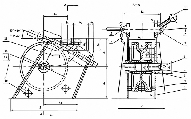
L | L1 | L2 | L3 | L4 | B | b1 | D | d1 | d2 | h1 | h2 | t | t1 | Weight (kg) |
| 44 | 42~44 | 1000 | 370 | 400 | 270 | 80 | 380 | 260 | 484 | 22 | 69 | 392 | 281 | 12 | 32 | 274 |
| 48 | 46~48 | 1050 | 420 | 450 | 300 | 85 | 446 | 286 | 528 | 26 | 73 | 414 | 306 | 12 | 34 | 351 |
| 52 | 50~52 | 1100 | 440 | 500 | 320 | 90 | 510 | 310 | 572 | 32 | 77 | 440 | 338 | 14 | 36 | 451 |
| 56 | 54~56 | 1150 | 450 | 550 | 340 | 92 | 556 | 316 | 600 | 34 | 81 | 460 | 354 | 15 | 38 | 536 |
| 60 | 58~60 | 1200 | 470 | 570 | 360 | 95 | 610 | 330 | 620 | 38 | 87 | 490 | 378 | 16 | 40 | 651 |
| 64 | 62~64 | 1250 | 500 | 600 | 370 | 100 | 666 | 346 | 640 | 40 | 94 | 520 | 400 | 17 | 42 | 753 |
| 68 | 66~68 | 1300 | 550 | 640 | 39 | 102 | 732 | 372 | 680 | 42 | 101 | 540 | 420 | 18 | 45 | 939 |
| 73 | 70~73 | 1350 | 570 | 670 | 41 | 110 | 800 | 400 | 730 | 45 | 109 | 580 | 460 | 20 | 48 | 1178 |
| 78 | 76~78 | 1400 | 610 | 700 | 442 | 115 | 865 | 425 | 780 | 48 | 116 | 630 | 490 | 22 | 50 | 1422 |
| 84 | 81~84 | 1460 | 650 | 740 | 475 | 120 | 940 | 454 | 840 | 50 | 124 | 670 | 530 | 24 | 55 | 1758 |
| 90 | 87~90 | 1540 | 710 | 780 | 507 | 135 | 1030 | 484 | 900 | 55 | 132 | 720 | 570 | 26 | 60 | 2171 |
| 95 | 92~95 | 1600 | 740 | 820 | 535 | 140 | 1080 | 508 | 950 | 58 | 139 | 760 | 610 | 28 | 65 | 2567 |
| 102 | 97~102 | 1680 | 790 | 870 | 572 | 145 | 1150 | 540 | 1020 | 60 | 148 | 800 | 650 | 30 | 70 | 2755 |
| 107 | 105~107 | 1750 | 840 | 900 | 600 | 150 | 1210 | 569 | 1070 | 63 | 154 | 860 | 690 | 32 | 75 | 3640 |
| 114 | 111~114 | 1820 | 880 | 940 | 637 | 160 | 1270 | 598 | 1140 | 68 | 163 | 910 | 740 | 34 | 80 | 4302 |
| 122 | 117~122 | 1880 | 930 | 1010 | 679 | 165 | 1340 | 632 | 1220 | 70 | 173 | 980 | 790 | 36 | 85 | 5326 |
| 132 | 124~132 | 1960 | 1000 | 1080 | 730 | 175 | 1440 | 674 | 1320 | 75 | 185 | 1060 | 860 | 38 | 90 | 6244 |
Selection & Inquiry Guide
Step 1: Confirm GB/T 3844-2000 roller bar / roller lever type and nominal diameter 44–132 according to the actual anchor chain diameter.
Step 2: Provide vessel installation position, windlass-to-hawse-pipe arrangement, chain entry angle, and chain exit angle so the chain stopper height and chain-line alignment can be checked.
Step 3: Confirm anchor chain grade, chain minimum breaking load, and classification requirement. The supplied design basis of 80% chain minimum breaking load should be verified against the vessel design and class approval scope.
Step 4: Confirm material requirements for the forged alloy steel stopper bar / gate bar, side wall plates, body, shaft, roller, and any material traceability requirement.
Step 5: Confirm surface treatment, NDE inspection scope, lubrication requirement, maker certificate or class certificate requirement, quantity, delivery destination, and required delivery time.
Step 6: Provide GA drawing, installation drawing, reference photos, or replacement sample information if the chain stopper is for a repair or retrofit project.
Structure
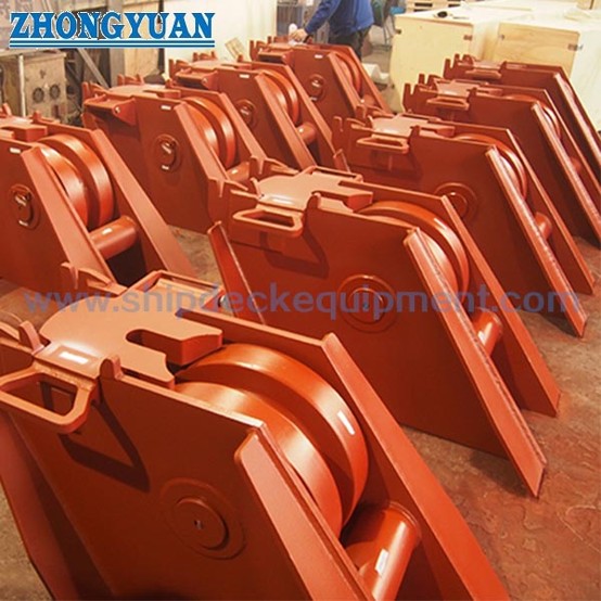
Deck-mounted chain stopper body | Roller bar / roller lever arrangement | Forged alloy steel stopper bar / gate bar | Reinforced side wall plates | Chain wheel / roller | Lubricated shaft | Chain holding interface | Mounting base | Project-specified coating
Anchor Chain Holding, Fabrication & Engineering Advantages
Custom Attributes
How It Works
Anchor chain runs through the stopper position → Chain wheel / roller guides the chain line → Forged alloy steel stopper bar / gate bar engages the chain link → Chain pull is transferred through reinforced side wall plates and stopper body to the deck foundation → Windlass holding load is reduced → Shaft lubrication supports flexible roller movement during operation
Applications
Ship anchoring arrangement | Anchor windlass deck area | Chain stopper between windlass and hawse pipe | Forecastle deck equipment | Cargo vessels | Tankers | Bulk carriers | Container vessels | Workboats | Newbuilding and repair replacement projects
Certifications & Advantages
Certificates can be arranged according to project requirement, inspection scope, material traceability, and class society approval procedure.
Certification: CCS, NK, BV, ABS, DNV, LR, KR, IRS, RS, RINA, CRS, Makers Test Certificate.
Drawing & Photos


FAQ
Q1: What information is needed to confirm chain stopper height?
A1: The vessel installation position, chain entry angle, chain exit angle, windlass and hawse pipe relationship, deck foundation arrangement, and actual chain diameter should be provided. These items affect chain-line alignment and whether the stopper bar meets the chain link correctly.
Q2: Is the 80% anchor chain minimum breaking load a product SWL?
A2: No. The supplied description states that the chain stopper is designed with reference to 80% of the anchor chain minimum breaking load. This should be treated as a design strength basis, not a direct webpage SWL declaration. Final selection should be checked with chain grade, vessel drawing, deck foundation, and class approval requirement.
Q3: Why use a forged alloy steel stopper bar and reinforced side wall plates?
A3: The stopper bar / gate bar is the critical chain-contact holding component, so forged alloy steel is used to support strength at the high-load contact area. The side wall plates are reinforced around the stopper position to help transfer anchor chain pull through the chain stopper body and deck foundation.