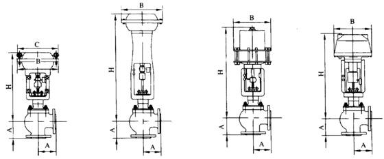
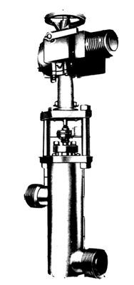
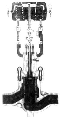
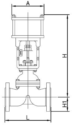
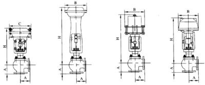
HPAS high-pressure single-seat angle valve is a top-guided control valve, featuring small pressure drop loss in the valve body, large flow rate and wide adjustable range. The angle valve can be selected according to the requirements of pipeline turning layout.
The valve core has a large guiding area and good vibration resistance. The control valve is equipped with a multi-spring diaphragm actuator, which has a compact structure and large output force. The angle valve can be widely used to control high-pressure fluids at various temperatures.
Cv value and stroke are shown in Table 1. |
Nominal diameter (mm) | 25 | 40 | 50 | 80 |
Valve seat diameter (mm) | | 25 | 32 | 40 | 32 | 40 | 50 | 50 | 65 | 80 |
Rated Cv value | Equal percentage linearity | JIS63K ANSI9001500 | 0.25 | 0.4 | 0.63 | 1 | 1.6 | 2.5 | 4 | 6.3 | 12 | 12 | 17 | 25 | 17 | 25 | 47 | 47 | 75 | 110 |
ANSI2500 | - | 12 | 17 | 12 | 17 | 31 | 31 | 47 | 75 |
Rated stroke (mm) | 14.3 | 25 | 38 |
Allowable pressure difference
I. Valves equipped with HA and VA actuators (with positioners) are shown in Tables 2 and 3.
A. Air-closed valves (Table 2) |
Nominal pressure | Actuator | Supply pressure (MPa) | Spring range (MPa) | Allowable pressure difference |
Valve seat diameter (mm) or Cv value |
Cv≤4.0 | Cv=6.3 | Cv=12 | 32 | 40 | 50 | 65 | 80 |
ANSI 900 1500 JIS 63K | HA3D | 0.28 | 0.04~0.20 | 16.3 15.2 | 16.1 14.9 | 10.2 9.2 | 5 4.2 | 3.2 2.7 | 1.8 1.4 | 1 0.70 | 0.70 0.40 |
0.3 | 20.7 19.6 | 20.5 19.2 | 13 12 | 6.4 5.7 | 4.2 3.6 | 2.4 1.9 | 1.4 1 | 0.90 0.60 |
0.35 | 26.4 | 26.4 | 20 19 | 10 9.2 | 6.6 6 | 3.8 3.4 | 2.3 1.9 | 1.6 1.3 |
0.4 | - | - | 26.4 26 | 13.5 12.8 | 9.1 8.5 | 5.3 4.8 | 3.2 2.8 | 2.2 1.9 |
HA4D | 0.28 | - | - | 18.3 17.3 | 9.1 8.4 | 6.1 5.5 | 3.5 3 | 2.1 1.7 | 1.4 1.1 |
0.3 | - | - | 23.1 22.1 | 11.6 10.9 | 7.7 7.1 | 4.5 4 | 2.7 2.3 | 1.9 1.6 |
0.35 | - | - | 26.4 | 17.7 17 | 11.9 11.3 | 7 6.5 | 4.2 3.9 | 3 2.7 |
0.4 | - | - | - | 23.9 23.2 | 16.1 15.5 | 9.5 9 | 5.8 5.4 | 4.1 3.8 |
VA5D | 0.26 | 0.02~0.10 | - | - | - | 26.3 25.5 | 17.7 17.1 | 10.4 10 | 6.3 6 | 4.5 4.2 |
0.28 | - | - | - | 26.4 | 20 19.4 | 11.8 11.4 | 7.2 6.8 | 5.1 4.8 |
ANSI 2500 | HA3D | 0.28 | 0.04~0.20 | 16.3 15.2 | 16.1 14.9 | 10.2 9.2 | 10.2 9.2 | 5 4.2 | 2.5 2 | 1.8 1.4 | 1 0.70 |
0.3 | 20.7 19.6 | 20.5 19.2 | 13 12 | 13 12 | 6.4 5.7 | 3.3 2.8 | 2.4 1.9 | 1.4 1 |
0.35 | 31.6 30.5 | 31.4 30.1 | 20 19 | 20 19 | 10 9.2 | 5.2 4.7 | 3.8 3.4 | 2.3 1.9 |
0.4 | 42.5 41.4 | 42.3 41 | 27 26 | 27 26 | 13.5 12.8 | 7.2 6.7 | 5.3 4.8 | 3.2 2.8 |
HA4D | 0.28 | - | - | 18.3 17.3 | 18.3 17.3 | 9.1 8.4 | 4.8 4.3 | 3.5 3 | 2.1 1.7 |
0.3 | - | - | 23.1 22.1 | 23.1 22.1 | 11.6 10.9 | 6.1 5.6 | 4.5 4 | 2.7 2.3 |
0.35 | - | - | 35.1 34.1 | 35.1 34.1 | 17.7 17 | 9.5 8.9 | 7 6.5 | 4.2 3.9 |
0.4 | - | - | 44 | 44 | 23.9 23.2 | 12.8 12.3 | 9.5 9 | 5.8 5.4 |
VA5D | 0.26 | 0.02~0.10 | - | - | - | - | 26.3 25.5 | 14.1 13.6 | 10.4 10 | 6.3 6 |
0.28 | - | - | - | - | 29.6 28.9 | 15.9 15.4 | 11.8 11.4 | 7.2 6.8 |
Remarks: - The maximum allowable pressure difference shall not exceed the maximum value specified in the ANSI B16.34 standard.
- The maximum allowable pressure difference varies with the valve seat leakage. The pressure difference given in the upper part of the same cell indicates the condition when the valve seat leakage is ≤0.01%, while the pressure difference in the lower part indicates the condition when the valve seat leakage is ≤0.001%.
- The inlet pressure P1 shall not exceed the maximum allowable pressure difference when the valve is closed.
|
B. Air-to-open valves Table 3 |
Nominal pressure | Actuator | Supply pressure (MPa) | Spring range (MPa) | Allowable pressure difference (MPa) |
Valve seat diameter (mm) or Cv value |
Cv≤4.0 | Cv=6.3 | Cv=12 | 32 | 40 | 50 | 65 | 80 |
ANSI 900 1500 | HA3R | 0.26~0.04 (*4) | 0.08~0.24 | 16.3 15.2 | 16.1 14.9 | 10.2 9.2 | 5 4.2 | 3.2 2.7 | 1.8 1.4 | 1 0.70 | 0.70 0.40 |
HA4R | 18.7 18 | 18.5 17.7 | 18.3 17.3 | 9.1 8.4 | 6.1 5.5 | 3.5 3 | 2.1 1.7 | 1.4 1.1 |
VA5R | - | - | - | 12.7 12 | 8.5 7.9 | 5 4.5 | 3 2.6 | 2.1 1.8 |
VA6R | 0.30(*1) | 0.19~0.25 | 26.4 | 26.4 | 26.4 | 25.8 | 17.4 | 10.2 | 6.2 | 4.4 |
0.35(*2) | 0.19~0.30 |
0.40(*3) | 0.19~0.35 | 26.4 | 26.4 | 26.4 | 25.1 | 16.8 | 9.8 | 5.9 | 4.1 |
ANSI 2500 | HA3R | 0.26~0.40 (*4) | 0.08~0.24 | 16.3 15.2 | 16.1 14.9 | 10.2 9.2 | 10.2 9.2 | 5 4.2 | 2.5 2 | 1.8 1.4 | 1 0.70 |
HA4R | 18.7 18 | 18.5 17.7 | 18.3 17.3 | 18.3 17.3 | 9.1 8.4 | 4.8 4.3 | 3.5 3 | 2.1 1.7 |
VA5R | 0.26~0.28 (*4) | - | - | - | - | 12.7 12 | 6.8 6.2 | 5 4.5 | 3 2.6 |
VA6R | 0.30(*1) | 0.19~0.25 | 32.9 | 32.8 | 32.7 | 32.7 | 25.8 | 13.8 | 10.2 | 6.2 |
0.35(*2) | 0.19~0.30 |
0.40(*3) | 0.19~0.35 | 32.5 | 32.3 | 32 | 32 | 25.1 | 13.3 | 7.8 | 5.9 |
II. Valves equipped with VP actuators (with positioners) are shown in Tables 4 |
公称压 力 | 执行 机构 | 供气 压力 (MPa) | 允许压差(MP) |
阀座直径(mm)或Cv值 |
Cv≤4.0 | Cv=6.3 | Cv=12 | 32 | 40 | 50 | 65 | 80 |
ANSI 900 1500 | VP5 | 0.3 | 18.8 18.5 | 18.7 18.4 | 18.6 18.2 | 18.4 17.7 | 14.2 13.6 | 8.3 7.9 | 5 4.7 | 3.6 3.3 |
0.4 | 25.1 24.8 | 25.1 24.7 | 25 24.5 | 24.7 24.1 | 19.1 18.5 | 11.3 10.8 | 6.9 6.5 | 4.9 4.6 |
0.5 | 26.4 | 26.4 | 26.4 | 26.4 | 24 23.4 | 14.2 13.8 | 8.7 8.3 | 6.2 5.9 |
VP6 | 0.3 | - | - | - | - | 17.9 17.5 | 14.6 14.2 | 8.9 8.6 | 6.4 6.1 |
0.4 | - | - | - | - | 24 23.6 | 19.7 19.2 | 12.1 11.7 | 8.6 8.3 |
0.5 | - | - | - | - | 26.4 | 24.8 24.3 | 15.2 14.8 | 10.9 10.6 |
VP7 | 0.3 | - | - | - | - | - | 17.5 17.1 | 13.8 13.5 | 9.9 9.6 |
0.4 | - | - | - | - | - | 23.4 23.1 | 18.6 18.2 | 13.3 13 |
0.5 | - | - | - | - | - | 26.4 | 23.3 22.9 | 16.7 16.4 |
ANSI 2500 | VP5 | 0.3 | 18.8 18.5 | 18.7 18.4 | 18.6 18.2 | 18.6 18.2 | 18.4 17.7 | 11.3 10.7 | 8.3 7.9 | 5 4.7 |
0.4 | 25.1 24.8 | 25.1 24.7 | 25 24.5 | 25 24.5 | 24.7 24.1 | 15.2 14.7 | 11.3 10.8 | 6.9 6.5 |
0.5 | 31.5 32.2 | 31.4 31.1 | 31.3 30.9 | 31.3 30.9 | 31 30.4 | 19.2 18.6 | 14.2 13.8 | 8.7 8.3 |
VP6 | 0.3 | - | - | - | - | - | 17.8 17.3 | 14.6 14.2 | 8.9 8.6 |
0.4 | - | - | - | - | - | 23.9 23.5 | 19.7 19.2 | 12.1 11.7 |
0.5 | - | - | - | - | - | 30 29.6 | 24.8 24.3 | 15.2 14.8 |
VP7 | 0.3 | - | - | - | - | - | - | 17.5 17.1 | 13.8 13.5 |
0.4 | - | - | - | - | - | - | 23.4 23.1 | 18.6 18.2 |
0.5 | - | - | - | - | - | - | 29.4 29 | 23.3 22.9 |
Remarks: - If the actuator is equipped with an auxiliary air supply, the smaller one of the two supply pressures shall be selected as the basis for calculating the allowable pressure difference.
- The maximum allowable pressure difference shall not exceed the maximum value specified in the ANSI B16.34 or JIS B2201 standard.
- The inlet pressure P1 shall not exceed the allowable pressure difference when the valve is closed.
- The maximum allowable pressure difference varies with the valve seat leakage. The pressure difference given in the upper part of the same cell indicates the condition when the valve seat leakage is ≤0.01%, while the pressure difference in the lower part indicates the condition when the valve seat leakage is ≤0.001%.
|
Flange distance is shown in Table 5. Table 5 Unit: mm |
Nominal diameter | A |
JIS63KRF | ANSI900 | ANSI1500 | ANSI2500 |
RF,SW,BW | RJ | RF,SW,BW | RJ | RF,SW,BW | RJ |
25 | 138 | 146 | 159 | 159 |
40 | 161.5 | 166.5 | 179 | 180.5 |
50 | 177 | 187.5 | 189 | 188 | 189 | 225 | 225 |
80 | 215.5 | 220 | 220 | 230 | 230 | 270 | 270 |

Equipped with HA,VA5,VA6,VP actuator