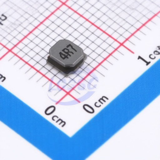
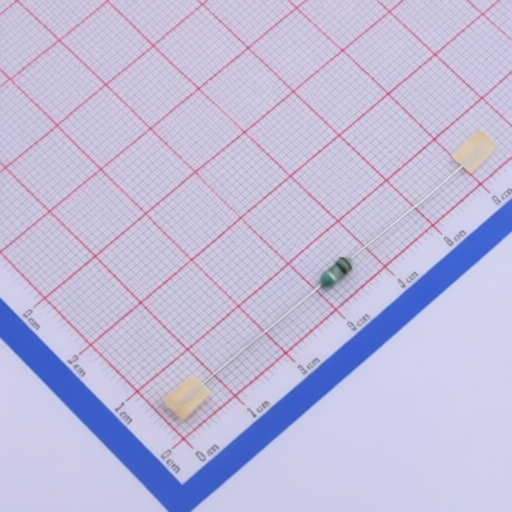
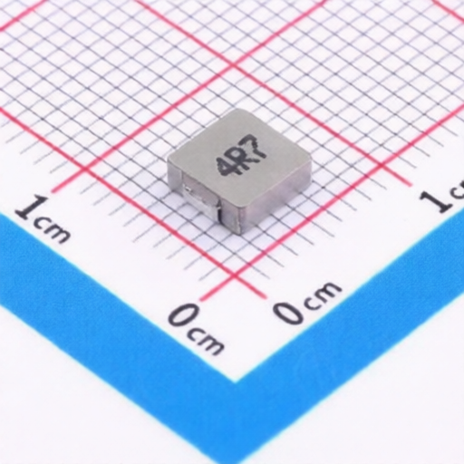
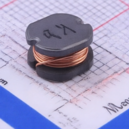
The FHW-UC Series Wire Wound Chip Inductors are designed for various electronic applications. These ceramic core inductors offer a range of inductance values from 2.2nH to 1000H with tight tolerances. They are manufactured with a ceramic core and copper wire, encapsulated with UV adhesive, and feature tin or gold plated terminals. The series is suitable for applications requiring reliable performance across a wide operating temperature range of -40 to +125 and meets stringent reliability testing standards.
| Part Number Prefix | Size | Core Type | Inductance Range (nH) | Tolerance | Operating Temperature Range | Dimensions (mm) L x W x T (Max) | Rated Current (mA) Max (Example for 10nH) | Self-Resonant Frequency (MHz) Min (Example for 10nH) | DC Resistance () Max (Example for 10nH) |
|---|---|---|---|---|---|---|---|---|---|
| FHW0805UC | 0805 (2012) | Ceramic Core | 2.2nH - 1000H | 2% (G), 5% (J), 10% (K) | -40 to +125 | 2.30 x 1.70 x 1.52 | 600 mA (for 10nH) | 4200 MHz (for 10nH) | 0.15 (for 10nH) |
| Specific Model Examples: | |||||||||
| FHW0805UC2N2GT | 0805 | UC (Ceramic) | 2.2nH | K (10%) | -40 to +125 | 2.30 x 1.70 x 1.52 | 800 mA | 8500 MHz | 0.03 |
| FHW0805UC10GT | 0805 | UC (Ceramic) | 10nH | G, J, K (2%, 5%, 10%) | -40 to +125 | 2.30 x 1.70 x 1.52 | 600 mA | 4200 MHz | 0.15 |
| FHW0805UCR10GT | 0805 | UC (Ceramic) | 100nH | G, J, K (2%, 5%, 10%) | -40 to +125 | 2.30 x 1.70 x 1.52 | 400 mA | 1200 MHz | 0.46 |
| FHW0805UC2R2GT | 0805 | UC (Ceramic) | 2.2H | J, K (5%, 10%) | -40 to +125 | 2.30 x 1.70 x 1.52 | 150 mA | 50 MHz | 4.20 |
| Dimensions (mm): | |||||||||
| Size | L (Max) | W (Max) | T (Max) | A | B | C | D | E | |
| 2012(0805) | 2.30 | 1.70 | 1.52 | 1.27 | 0.50 | 1.78 | 1.02 | 0.76 | |
| Item | Requirements | Test Methods and Remarks |
|---|---|---|
| Operating Temperature Range | -40+125 | FHW-UC series |
| Solder Ability | Electrode surface solder coverage 90% | Dip in solder (96.5Sn/3.0Ag/0.5Cu) at 2455 for 51s. |
| Resistance to Soldering | Inductance change 5%; Q value change 10% | Dip in solder (96.5Sn/3.0Ag/0.5Cu) at 2605 for 101s. |
| Vibration | Inductance change 5%; Q value change 10% | Amplitude 1.5mm, frequency 10~55Hz, 2 hours per direction (X, Y, Z). |
| Adhesion of electrode | No electrode detachment after test. | Weld on PCB, apply force as specified (0805UC Series: 20N, 101s, 1.0 mm/s). |
| Low temperature resistance | Inductance change 5%; Q value change 10% | -402 for 1000 +24/-0 h. |
| High temperature resistance | Inductance change 5%; Q value change 10% | +1255 for 1000 +24/-0 h. |
| Temperature Shock | Inductance change 5%; Q value change 10% | +125 (30 min) -40 (30 min), 100 cycles. |
| High temperature load | Inductance change 5%; Q value change 10% | 1252 for 1000 +24/-0 h with rated current applied. |
| Static Humidity | Inductance change 5%; Q value change 10% | 90%95%RH at 602 for 1000 +24/-0 h. |
| Bending strength | No visible mechanical damage. | Install on PCB, apply force vertically, bend plate 20.2 mm at 10.5 mm/s, hold 201s. |
| Solvent Resistance | Inductance change 5%; Q value change 10% | Soak in isopropyl alcohol at 235 for 50.5 min. |
| Size | Pieces per Reel | Pieces per Box | Pieces per Case |
|---|---|---|---|
| 0805 | 3000 | 9000 (3 Reels) - 180000 (6 Reels) | 45000 (1.5 Boxes) - 120000 (4 Boxes) |
Soldering Method: Reflow soldering
Flux: Rosin-based flux, avoid highly acidic flux with halide content exceeding 0.2(wt)%.
Solder: Lead-free solder (96.5Sn /3.0Ag/0.5Cu).
Temperature Difference: Max 150 between solder and ferrite surface during pre-heating. Max 100 between product surface and solvent during cooling.
Hand Soldering: Soldering Iron Temperature: 350 (Max), Power: 30W (Max), Dwell Time: < 5S. Avoid touching coil and encapsulation layer.
The company does not use ODS such as CCl4 (Carbon Tetrachloride) and HCFC in its production processes.