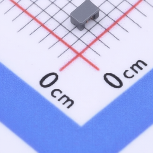
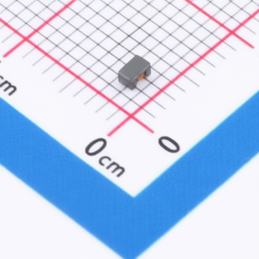
The FDCW2012 series wire wound chip common mode choke coil offers excellent noise suppression performance due to its high common mode impedance at high frequencies. Designed for compact and low-profile applications, these coils measure 2.0*1.2*1.2 mm. They are 100% Lead (Pb) & Halogen-Free and RoHS compliant. Applications include power switches, servers, telecommunication systems, USB communication, LCD panel links, and countering common mode noise in high-speed lines.
| Part Number | Common Mode Impedance (Z @100MHz) ( 25%) | DCR (m MAX) | IR (mA MAX) | Rated Voltage (Vdc) | Dimensions (L x W x H) (mm) | Operating Temperature Range (C) |
|---|---|---|---|---|---|---|
| FDCW2012-2-300TF | 30 | 200 | 10 | 50 | 2.0 x 1.2 x 1.2 | -40 to +85 |
| FDCW2012-2-500TF | 50 | 250 | 10 | 50 | 2.0 x 1.2 x 1.2 | -40 to +85 |
| FDCW2012-2-750TF | 75 | 250 | 10 | 50 | 2.0 x 1.2 x 1.2 | -40 to +85 |
| FDCW2012-2-900TF | 90 | 300 | 10 | 50 | 2.0 x 1.2 x 1.2 | -40 to +85 |
| FDCW2012-2-121TF | 120 | 300 | 10 | 50 | 2.0 x 1.2 x 1.2 | -40 to +85 |
| FDCW2012-2-161TF | 160 | 350 | 10 | 50 | 2.0 x 1.2 x 1.2 | -40 to +85 |
| FDCW2012-2-181TF | 180 | 350 | 10 | 50 | 2.0 x 1.2 x 1.2 | -40 to +85 |
| FDCW2012-2-201TF | 200 | 350 | 10 | 50 | 2.0 x 1.2 x 1.2 | -40 to +85 |
| FDCW2012-2-221TF | 220 | 350 | 10 | 50 | 2.0 x 1.2 x 1.2 | -40 to +85 |
| FDCW2012-2-251TF | 250 | 400 | 10 | 50 | 2.0 x 1.2 x 1.2 | -40 to +85 |
| FDCW2012-2-261TF | 260 | 400 | 10 | 50 | 2.0 x 1.2 x 1.2 | -40 to +85 |
| FDCW2012-2-301TF | 300 | 400 | 10 | 50 | 2.0 x 1.2 x 1.2 | -40 to +85 |
| FDCW2012-2-361TF | 360 | 400 | 10 | 50 | 2.0 x 1.2 x 1.2 | -40 to +85 |
| FDCW2012-2-371TF | 370 | 450 | 10 | 50 | 2.0 x 1.2 x 1.2 | -40 to +85 |
| FDCW2012-2-481TF | 480 | 550 | 10 | 50 | 2.0 x 1.2 x 1.2 | -40 to +85 |
| FDCW2012-2-501TF | 500 | 550 | 10 | 50 | 2.0 x 1.2 x 1.2 | -40 to +85 |
| FDCW2012-2-601TF | 600 | 550 | 10 | 50 | 2.0 x 1.2 x 1.2 | -40 to +85 |
| FDCW2012-2-671TF | 670 | 600 | 10 | 50 | 2.0 x 1.2 x 1.2 | -40 to +85 |
| FDCW2012-2-681TF | 680 | 700 | 10 | 50 | 2.0 x 1.2 x 1.2 | -40 to +85 |
| FDCW2012-2-751TF | 750 | 800 | 10 | 50 | 2.0 x 1.2 x 1.2 | -40 to +85 |
| FDCW2012-2-801TF | 800 | 1000 | 10 | 50 | 2.0 x 1.2 x 1.2 | -40 to +85 |
| FDCW2012-2-901TF | 900 | 1000 | 10 | 50 | 2.0 x 1.2 x 1.2 | -40 to +85 |
| FDCW2012-2-102TF | 1000 | 1000 | 10 | 50 | 2.0 x 1.2 x 1.2 | -40 to +85 |
| Dimension (mm) | A | B | C | D (TYP) | E (TYP) |
|---|---|---|---|---|---|
| Values | 2.000.20 | 1.200.20 | 1.200.20 | 0.5 | 0.5 |
| Reliability Test Item | Requirements | Test Methods and Remarks |
|---|---|---|
| Operating Life | 1. No visible mechanical damage 2. Impedance change: Within 20% 3. Insulation resistance10M min | 1. Reflow 2 times 2. temperature: 155 2 |
| Resistance to Soldering Heat | 1. No visible mechanical damage 2. Impedance change: Within20% | 1. Solder on PCB to Reflow test Peak Temp. 2605510 secs ,Cycles :2 times. Re-flowing Profile: Please refer to Fig-1 2. Test board thickness: 1.5mm 3. Test board material: glass epoxy resin 4. The specimen shall be stored at standard atmospheric conditions for 1 hour, after which the measurement shall be made. product showed no damage under microscope. |
| High Temperature | 1. No visible mechanical damage 2. Impedance change: Within 20% 3. Insulation resistance10M min | 1. Temperature: 1252 2. Duration: 1000 hours 3. The specimen shall be stored at standard atmospheric conditions for 1 hour, after which the measurement shall be made. |
| Steady Damp-Heat | 1. No visible mechanical damage 2. Impedance change: Within 20% 3. Insulation resistance10M min | 1. Temperature:85 2. Humidity: 85% RH 3. Duration:1000 hours 4. The specimen shall be stored at standard atmospheric conditions for 1 hour, after which the measurement shall be made. |
| Mechanical Vibration | 1. No visible mechanical damage 2. Impedance change: Within 20% | 1. Frequency: 10HZ55HZ10HZ/Min Cycles 2. Amplitude: 1.5 mm 3. Directions: X,Y,Z 4. Time: 2 hours in each directions (total of 6 hours) |
| Thermal Shock | 1. No visible mechanical damage 2. Impedance change: Within 20% 3. Insulation resistance10M min | 1. Temperature and time: -40for 303 min125for 303min, please refer to Fig-2 2. Transforming interval: Max. 3 Min 3. Tested cycle: 1000 cycles 4. The specimen shall be stored at standard atmospheric conditions for 1 hour, after which the measurement shall be made. |
| Salt Spray | 1. No visible mechanical damage 2. Impedance change: Within 20% | 1. Salt concentration: (5 1)% (mass percent) 2. pH value:6.5 - 7.2 3. temperature: 35 2 4. humidity: 85% 5. time: 24 hours 6. in normal temperature and humidity for 1 2 hours, testing inductance, the inductance value change can not be more than before test 10%. |
| Terminal Strength | No visible mechanical damage | 1. The electrode of the inductor is soldered to the PCB, to Fig-3 Then apply a force in the direction of the arrow. 2. 5N force. 3. Keep time: 10(1)s The first three tests were OK, and the force was applied until the peak value of the product peeling. The test speed was set in the range of 3 ~ 8mm/min. |
| Packaging Type | W (mm) | P1 (mm) | A0 (mm) | B0 (mm) | K0 (mm) | t (mm) | E (mm) | F (mm) | P2 (mm) | D0 (mm) | D1 (mm) | P0 (mm) |
|---|---|---|---|---|---|---|---|---|---|---|---|---|
| FDCW 2012 | 8.00 0.10 | 4.00 0.10 | 1.50 0.10 | 2.30 0.10 | 1.45 0.10 | 0.20 0.05 | 1.75 0.10 | 3.50 0.10 | 2.00 0.10 | 1.55 0.05 | 0.80 0.05 | 4.00 0.10 |
| Type | Standard Quantity | Reel | Inner box | Carton box |
|---|---|---|---|---|
| FDCW2012 | 2000 pcs / reel | 5Reel / box (10000 pcs) | 10 Middle boxes, (100000 pcs) |
| Packaging Type | A (mm) | B (mm) | C (mm) |
|---|---|---|---|
| Inner box | 188 | 195 | 67 |
| Carton Packaging Type | L (mm) | W (mm) | H (mm) |
| Carton | 390 | 350 | 215 |
| Reel Label | Content |
|---|---|
| Label on the reel | Customer's part Number Lot Number Quantity date code |
| Shipping Label | Customer's part Number Manufacturer's part Number Quantity date code |
| Peel force of top cover tape | Requirements |
|---|---|
| The peel speed shall be about 300mm/minute. The peel force of top cover tape shall be between 10 to 100gf. |