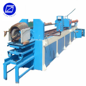
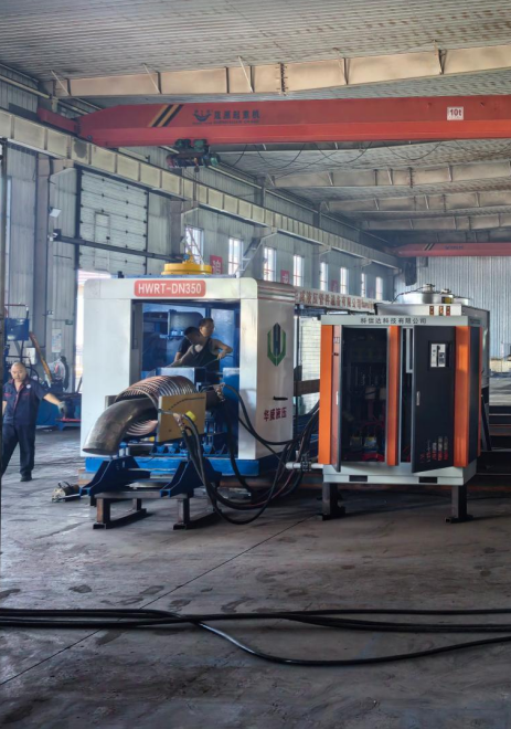
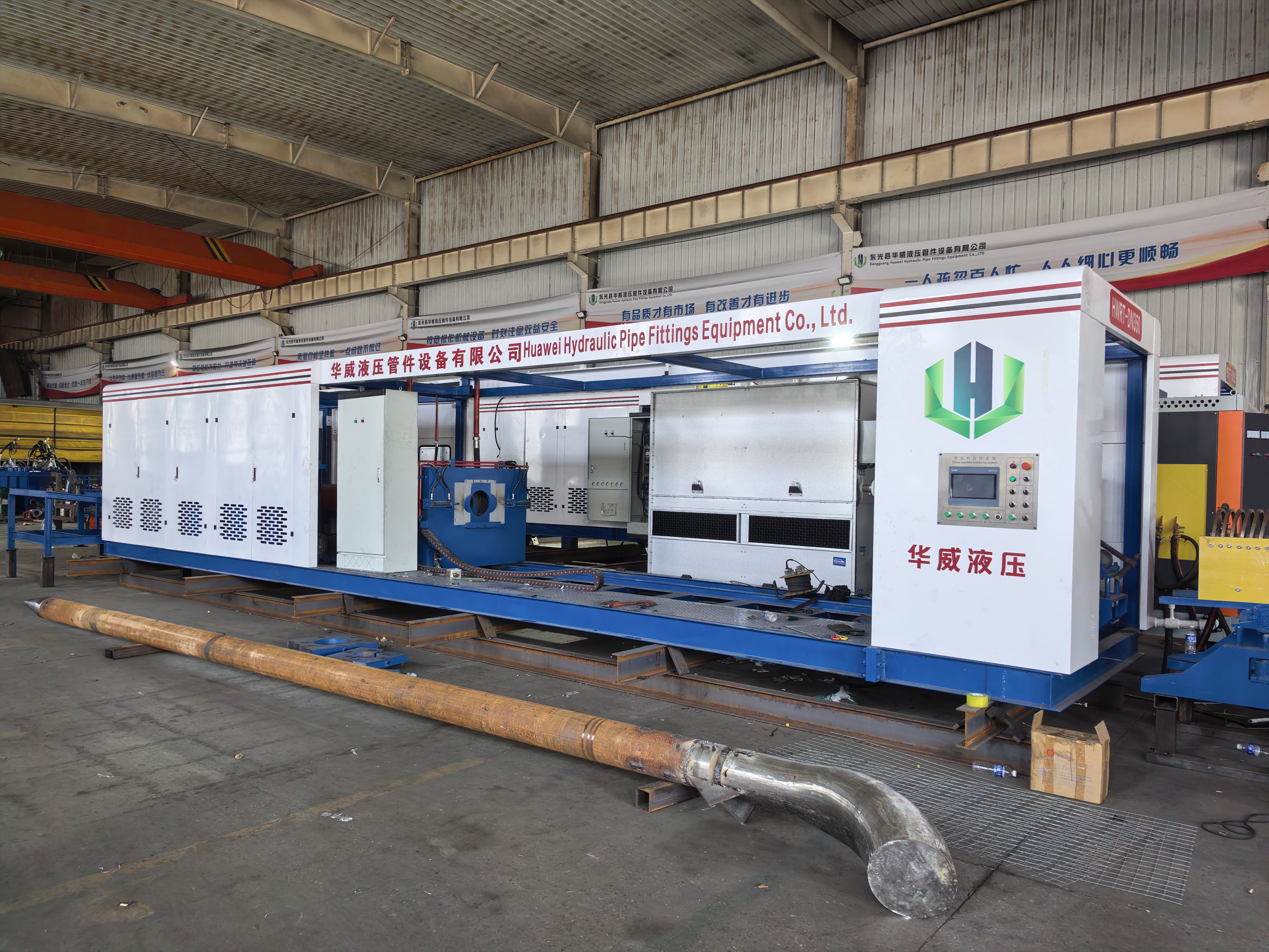
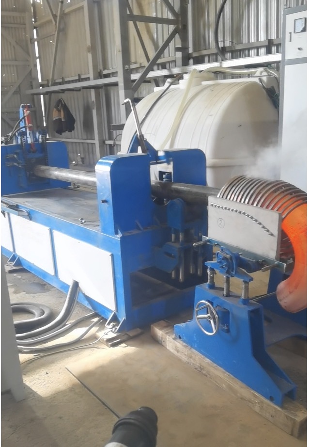
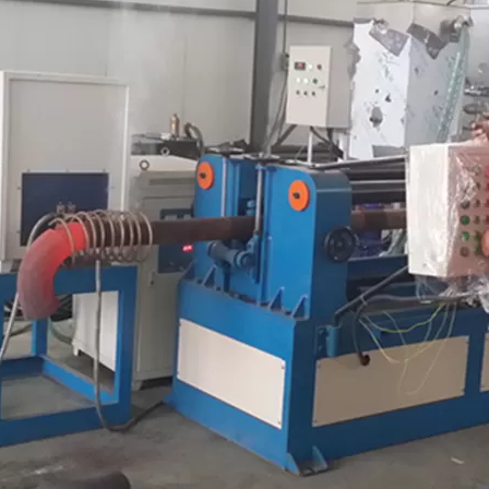
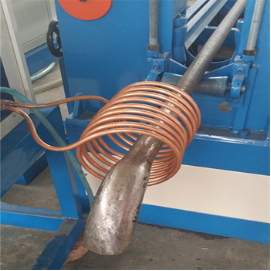
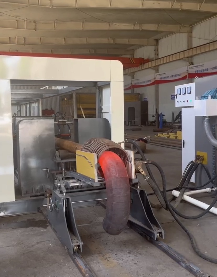
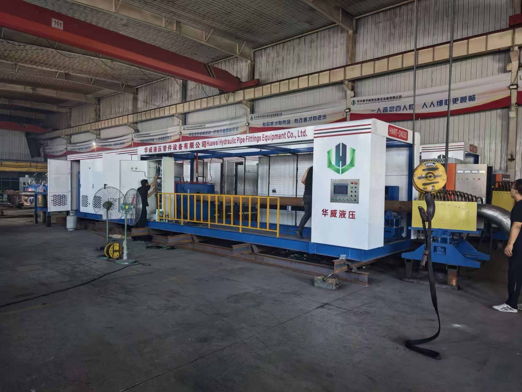
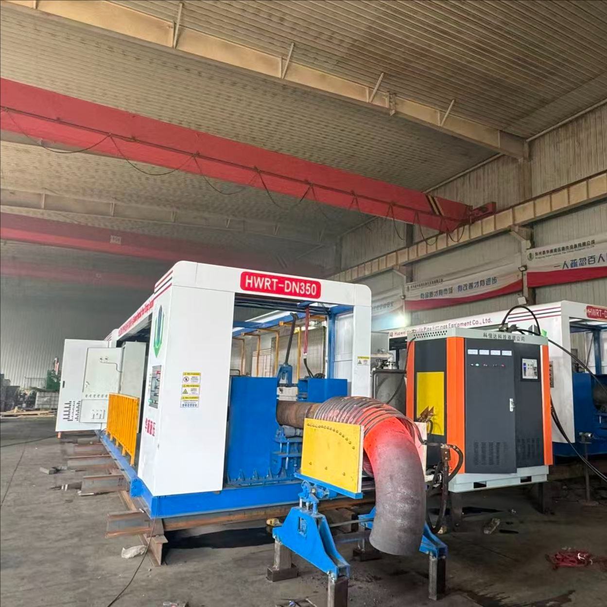
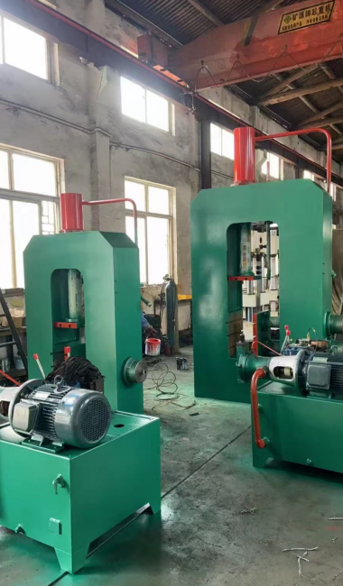
Elbow Hot Forming Machine (1"–4") — a hydraulic hot-pushing elbow making machine engineered for continuous industrial production of carbon steel and alloy steel elbows.
Performance & Working Range
Maximum push elbow diameter: 114 mm; minimum elbow diameter: 33.4 mm.
Rated for continuous 24-hour daily operation; air must be non-corrosive.
The equipment must be installed indoors in a workshop with sufficient operating space.
Oil Cylinder Construction
Manufactured in accordance with JB/T10205-2000 and JB/T15622-2005 standards.
Cylinder body in 45# steel with inner surface finish Ra0.4; piston rod in 45# seamless tube, chrome plated and polished to Ra0.3 with no straight or spiral lines.
Remaining cylinder parts are 45# forgings to guarantee mechanical properties.
Piston guide sleeve of the main oil cylinder uses a copper sleeve; all seals follow the standard priority series, with the main oil seal imported from AiKE (Austria).
Before assembly, smoothness, hardness, fit dimensions, forging quality and seal quality are inspected; a pressure test is carried out after assembly.
Main Oil Cylinder Parameters
Main cylinder thrust: 62 tons (two cylinders)
Structure: Piston structure with front and rear flanges
Test pressure: 31.5 MPa
Working pressure: 0–25 MPa
Main oil cylinder inner diameter: 125 mm
Main oil cylinder outer diameter: 150 mm
Piston rod diameter: 90 mm
Main oil cylinder material: 45# steel
Effective stroke of main oil cylinder: 2.5 m
Main Engine Structure
The main engine consists of the bottom frame, oil cylinder support plate, movable push plate, front baffle and tug boat.
The body is welded and assembled from Q235A medium plate, channel steel and round steel.
Push plate and bottom frame use an upper pulley and guide rail structure for smooth operation.
Front baffle and cylinder are fitted with a hydraulic mandrel regulating cylinder.
Main Engine Material Table
Title
Material Specifications & Models
Material
Note
Oil cylinder baffle
Steel plate 16 mm, 3 mm
Q235
—
Active push board
Steel plate 16 mm, 3 mm
Q235
—
Head board
Steel plate 16 mm, 3 mm
Q235
—
Foundation
U-steel 20#
Q235
—
Adjust the roller
Diameter 120 mm
45# steel
—
Cylinder support bracket
Steel plate 22 mm, 3 mm
Q235
—
Hydraulic Pump Station
Maximum working pressure of the hydraulic system: 25 MPa; test pressure: 31.5 MPa.
Inner and outer surfaces of the oil tank are rust-prevention treated; the tank is fitted with a filter screen, liquid level indicator and oil temperature display.
The entire hydraulic system is cleaned before oil injection and trial operation.
The pump station uses integrated block connections for stable, leak-free operation.
Three-Stage Pump Station Design
Stage 1: Design flow 25 L/min (high-pressure main pump), equipped with an electromagnetic speed-regulating motor for pipe bending and pushing.
Stage 2: Design flow 32 L/min (gear pump), equipped with a common four-stage motor for fast forward and fast backward. Maximum forward speed 2000 mm/min; maximum fast backward speed 2500 mm/min.
Stage 3: Design flow 10 L/min (gear pump), used for door lifting, core bar adjustment and other auxiliary hydraulic actions.
Component Specification & Model
No.
Title
Model
Qty
1
Oil pump
25SCY
1
2
Oil pump
CB-FC25-4FAS-R
—
5
Oil pump
CB-FC10-2FAS-R
1
7
Motor
11KW-4
1
8
Motor
7.5KW-4
1
9
Motor
2.2KW-6
1
10
Hand-operated direction valve
34SM-L20H-W
1
11
In-line check valve
PIF-L32H
5
13
Overflow valve
YF-B10H3
3
14
Multiple directional control valve
ZS-L010E2O
1
15
Multiple directional control valve
ZS-L010E3O
1
18
Electromagnetic relief valve
YFDH-L50H4
1
19
Hydraulic pressure indicator
YB-60
2
20
Electro-hydraulic directional valve
34DYO-L50H-T
1
21
Strainer
—
1
22
Controllable check valve
4D2
1
Design Configuration
Hydraulic propulsion with stepless speed regulation.
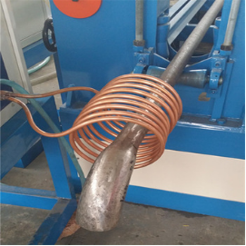
High-frequency heating, power 80 KW.
Manual feeding.
Manual insert board, lead screw tug wheel and manual gate.
Power supply and all motor operation controls are centralized in one operating cabinet, covering power supply shutdown, circuit breaking and cooling water pump start/stop.