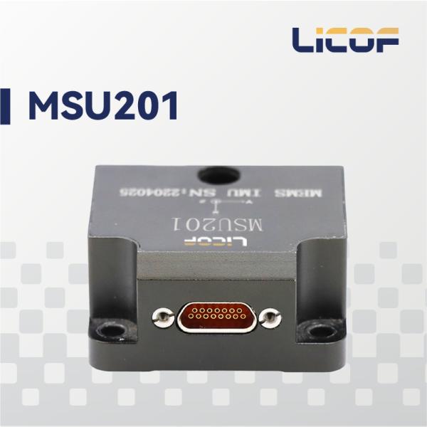
The LKF-MSU201 High-Dynamic MEMS Inertial Measurement Module is a reliable and cost-effective six-axis MEMS inertial navigation system, widely applicable in navigation, control, and measurement scenarios involving satellites, vehicles, ships, and UAVs. The module integrates high-performance MEMS gyroscopes and accelerometers within a compact, standalone structure. All electronic components in the system are 100% domestically manufactured, and the selected inertial sensors represent the cutting edge of MEMS technology.
Advanced Technology and Process
The three-axis MEMS gyroscopes measure angular motion, while the three-axis MEMS accelerometers sense linear acceleration. The system performs full-temperature compensation for bias, scale factor, misalignment, and g-dependent errors, ensuring long-term measurement accuracy across a wide range of conditions.
Precision Manufacturing and Calibration
Our company has accumulated a set of core technologies during the development of this product, ensuring its superior performance. The system employs high-speed sampling, static and dynamic error compensation techniques to deliver optimal performance during user operation.
Table1 Performance parameters of LKF-MSU201
Gyroscope | |
Range (°/s) | ±500 |
Bias over full temperature range (°/h) | ≤50 |
Bias stability (°/h, 10s smoothing) | ≤5 |
Bias stability (°/h, Allan,typical) | 0.5 |
Bias repeatability (°/h) | ≤3 |
Angular Random Walk (°/√h) | ≤0.3 |
Scale factor nonlinearity (ppm) | ≤150 |
Threshold / Resolution (°/h) | ≤3 |
Bandwidth (Hz) | 200 |
Accelerometer | |
Range (g) | ±50 |
Bias over full temperature range (mg) | ≤3(XY);≤5(Z) |
Bias stability (μg, 10s smoothing) | ≤100 |
Bias stability (μg, Allan variance) | ≤30 |
Bias repeatability (μg) | ≤300 |
Velocity Random Walk (mm/s/√h) | ≤40 |
Scale factor nonlinearity (ppm) | ≤500 |
Threshold / Resolution (μg) | ≤50 |
Adjustable Bandwidth (Hz) | 150 |
Electrical / Mechanical Interface | |
Power Supply (V) | 5-12 |
Power Consumption (W) | 1.5 |
Startup Time (s) | 2 |
Communication Interface | 1 × RS-422, 2 × RS-232, 1 × Synchronous TTL Output, 1 × Synchronous TTL Input |
Data Update Rate (Hz) | 200 (configurable, up to 1kHz) |
Dimensions (mm×mm×mm) | 44.8×38.6×21.5 |
Weight (g) | 50±5 |
Working Environment | |
Operating Temperature | -40°C~80°C |
Storage Temperature | -55°C~85°C |
Vibration (g, Rms) | 6.06 |
Shock (g) | 1000g/1ms (powered) |
Table 2 Connector Pin Definitions
Pin | Definition | Note |
8 | POWER_IN | Power supply: 5~12V |
15 | GND | |
6 | RS232_TXD1 | Reserved |
5 | RS232_RXD1 | |
3 | GND | |
10 | RS422 R+ | RS422 interface |
2 | RS422 R- | |
9 | RS422 T+ | |
1 | RS422 T- | |
14 | RS232_TXD2 | Reserved, receives external satellite RMC sentence for timestamping |
7 | RS232_RXD2 | |
13 | GND | |
11 | PPS_IN | PPS signal input, compatible with GNSS |
4 | TOV | General-purpose I/O, 3.3V logic, rising-edge triggered |
12 | GND |
Main Features
100% Domestically Sourced Components
High-Dynamic Performance With Large-Range Accelerometer on X-Axis
Compact Size, Low Weight, and Low Power Consumption
Full-Temperature Calibration and Compensation From -45°C to +80°C
1 kHz High-Speed Sampling
Resistant to Harsh Mechanical Environments
Supports Online Software Upgrades
Applications
Vehicle Positioning and Orientation
Radar/Infrared Antenna Stabilization Platform
UAV Attitude Reference/Trajectory Control
Vehicle and Vessel Attitude Measurement
Port Surveying Systems
On-the-Move Communication (OTMC)
Drilling and Extraction Systems
Mobile Mapping Systems
Satellite Applications
Automated Driving Test Systems
Figure 1 Dimension