Custom 1.5kW Low Loss PQ5033 High Frequency Planar Transformer for EV Charger OBC
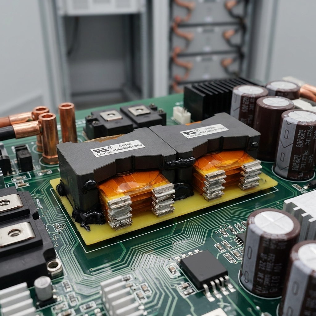
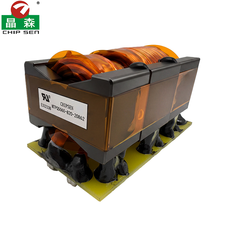
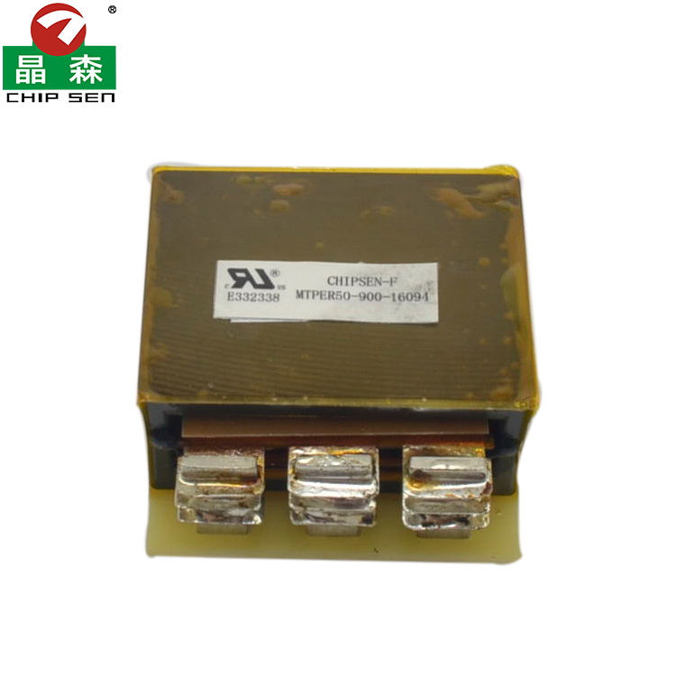
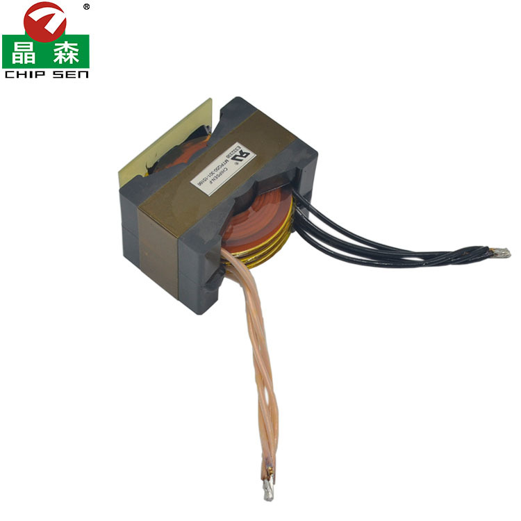
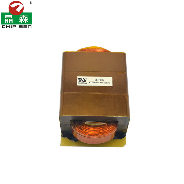
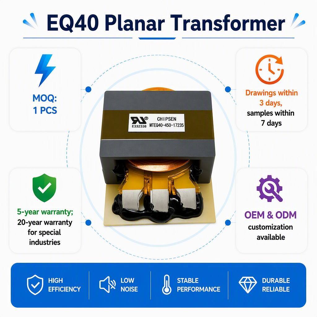
This 1.5 kW PQ5033 planar transformer is purpose-built for EV on-board chargers (OBC), DC-DC converters and LLC resonant power stages. Instead of conventional round magnet wire, the windings are realized as etched copper layers inside a multilayer PCB, terminated with heavy copper clip terminals for low contact resistance and high current capability. The result is a transformer with excellent turn-to-turn consistency, very low leakage inductance, low AC loss at high switching frequency and a low-profile footprint that fits the tight height budget of automotive power modules.Key Advantages
- Planar PCB Winding — Repeatable Electrical Performance: Winding geometry is fixed by the PCB artwork, so leakage inductance and turns ratio are virtually identical unit to unit — critical for LLC resonant tank tuning in mass production.
- Low Loss at High Frequency: Wide flat conductors minimize skin and proximity effect, keeping AC resistance low in the 100 kHz–500 kHz range where round-wire designs start to heat up.
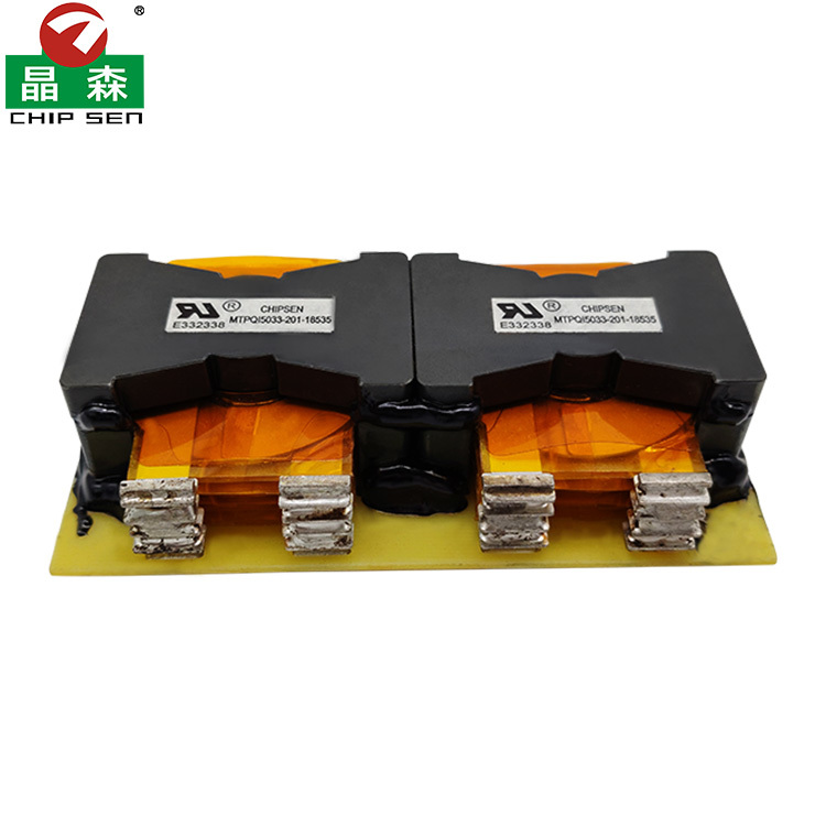
- Dual PQ5033 Core Set — High Power Density: Paired ferrite cores share the flux and thermal load, supporting continuous 1.5 kW throughput in a compact package.
- Copper Clip Terminals: Heavy-gauge tinned copper clips carry high primary/secondary current with minimal terminal loss, and provide a robust mechanical joint under automotive vibration.
- Superior Thermal Behaviour: The large flat surface area of the planar structure conducts heat directly into the PCB and heatsink, giving a lower hot-spot temperature than a wound bobbin of the same rating.
- UL Recognized Materials: Constructed with UL-listed insulation and core materials, UL File No. E332338.
- Fully Custom Engineered: Turns ratio, layer stack-up, magnetizing and leakage inductance, terminal layout and core gap all designed to your converter topology.
Technical Specifications
| Product Type | High Frequency Planar Transformer |
|---|
| Model Number | PQ5033 (MTPQI5033-201-18535) |
|---|
| Rated Power | 1.5 kW (continuous, forced-air cooled) |
|---|
| Core Type / Set | Dual PQ5033 Ferrite Core Set |
|---|
| Core Material | Low-loss high-frequency ferrite (PC95 / DMR95 class) |
|---|
| Winding Structure | Multilayer PCB planar winding, pure copper foil |
|---|
| Terminal Type | Tinned copper clip terminals, PCB mounting |
|---|
| Operating Frequency | 100 kHz – 500 kHz |
|---|
| Topology Compatibility | LLC Resonant / Phase-Shift Full Bridge / DAB |
|---|
| Turns Ratio | Customized to customer specification |
|---|
| Insulation Class | Class F (155 °C) / Class H (180 °C) available |
|---|
| Dielectric Strength | 3000 VAC / 1 min (Primary – Secondary) |
|---|
| Temperature Rise | ≤ 40 K at rated load |
|---|
| Operating Temperature | −40 °C ∼ +125 °C |
|---|
| Safety Reference | UL File No. E332338 (recognized component materials) |
|---|
| Customization | OEM / ODM accepted, designed to customer drawing |
|---|
| Place of Origin | China |
|---|
Planar vs. Conventional Wound Transformer
| Item | Planar (this product) | Conventional Wound |
|---|
| Profile Height | Low, fits slim OBC housings | Tall bobbin structure |
| AC Loss @ HF | Low — wide flat conductor | Higher skin / proximity loss |
| Parameter Consistency | Excellent, defined by PCB artwork | Depends on winding operator |
| Thermal Dissipation | Large flat surface, easy heatsinking | Heat trapped inside bobbin |
| Leakage Inductance | Low and tightly controlled | Larger spread batch to batch |
Typical Applications
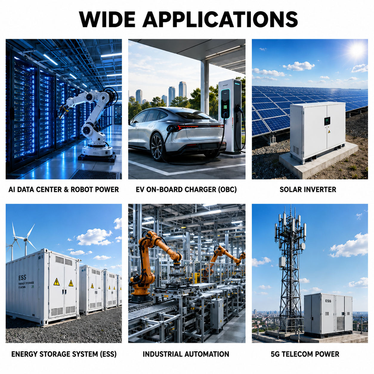
● EV On-Board Charger (OBC)
● DC-DC Converter Modules
● DC EV Charging Piles
● LLC Resonant Power Supplies
● Server & Telecom Power Modules
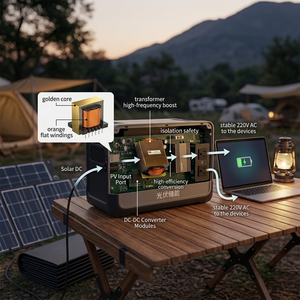
● Energy Storage & PV Micro-Inverters
Custom Design Process
- Share your requirement — topology, input/output voltage, power, switching frequency, height limit.
- Design proposal — our magnetics engineers return core selection, layer stack-up, turns ratio and expected loss/temperature rise.
- Sample build & test — prototype with full test report (Lm, Lk, turns ratio, DCR, Hi-Pot).
- Design freeze & mass production — controlled process, batch traceability, 100% electrical testing.
Packaging & Delivery
- Inner packing: anti-static bag / partition tray
- Outer packing: 5-layer export carton, wooden pallet on request
- Sample lead time: 10 – 15 working days (custom design)
- Mass production: 20 – 30 working days after design freeze
- Trade terms: EXW / FOB / CIF
FAQ
Q1: Can you design the planar transformer to our OBC schematic?
Yes. Send us the topology, input/output specification, switching frequency and mechanical height limit, and we will return a full design proposal with calculated loss and temperature rise.
Q2: Is the PCB winding included, or do we integrate it into our main board?
Both options are supported. We can supply the transformer as a complete assembly with its own winding PCB and copper clip terminals, or design the winding layers for integration into your motherboard.
Q3: What leakage inductance tolerance can you hold?
Because the winding geometry is defined by the PCB, leakage inductance spread is far tighter than a hand-wound part. The exact tolerance is confirmed on the approved sample and controlled in production.
Q4: What test reports do you provide?
Magnetizing inductance, leakage inductance, turns ratio, DCR, Hi-Pot and temperature-rise data can be supplied with each shipment on request.
Send us your OBC specification today — our planar magnetics engineers will reply with a custom design proposal and quotation within 24 hours.