Specifications
Model Number :
EE65
Installation :
SMD LEAD
MOQ :
1K
Delivery Time :
7-14 work days (Negotiable)
Frequency Range :
200 kHz to 700 kHz
Leakage Inductance :
< 0.2% to 0.5% of Primary Inductance
Customize Design :
Available for OEM projects
Payment Terms :
T/T
Operation Temperature :
-40℃ to +125℃
Powerrating :
Varies by model
Power :
180W
Clearance Distance :
≥ 6.0mm
Brand Name :
CHIPSEN
Output Current :
50A - 150A
Place of Origin :
China
Core Material :
PC40 / PC44 Ferrite
Price :
$8.5-11.8/pieces
Pad Size :
23.5*19.5mm
Frequencyrange :
Up to MHz range
Supply Ability :
10000pcs
Customization :
OEM / ODM Accepted
Core Type :
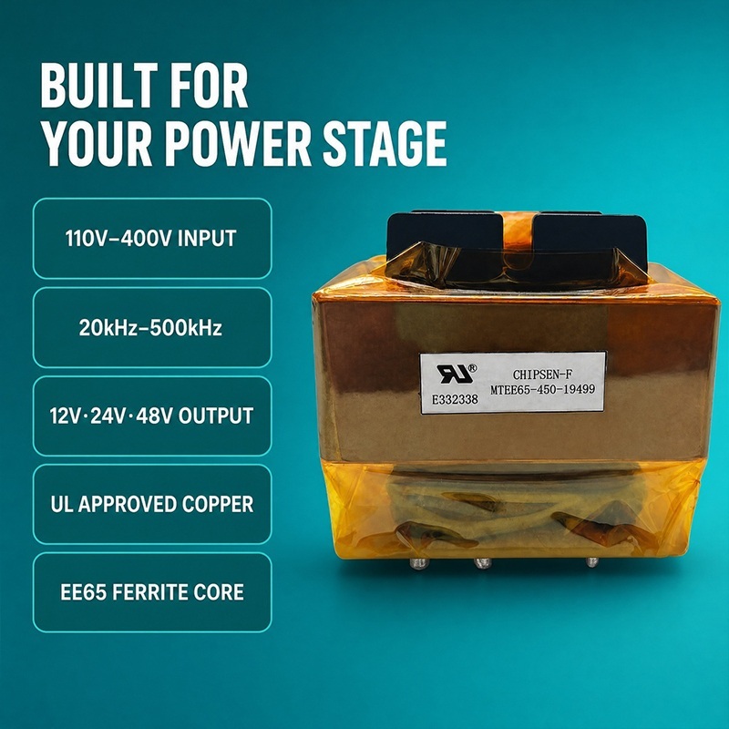
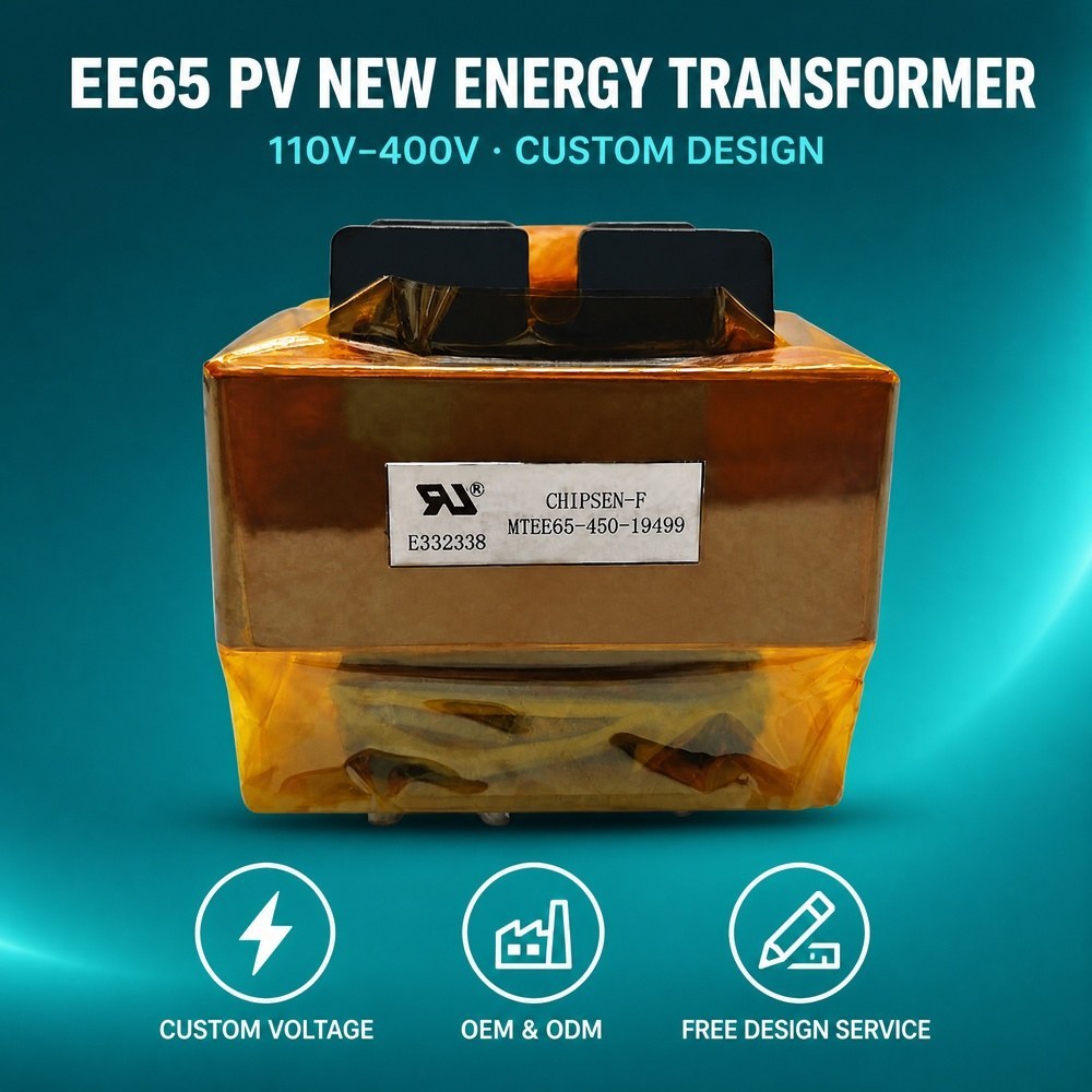
EE65 Ferrite Core
Certification :
UL/cUL Class B/F/H, VDE, CQC
Isolation Voltage :
Typically 1500V or higher
Description
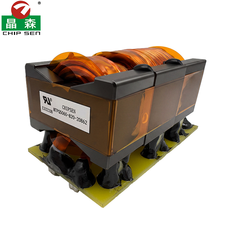
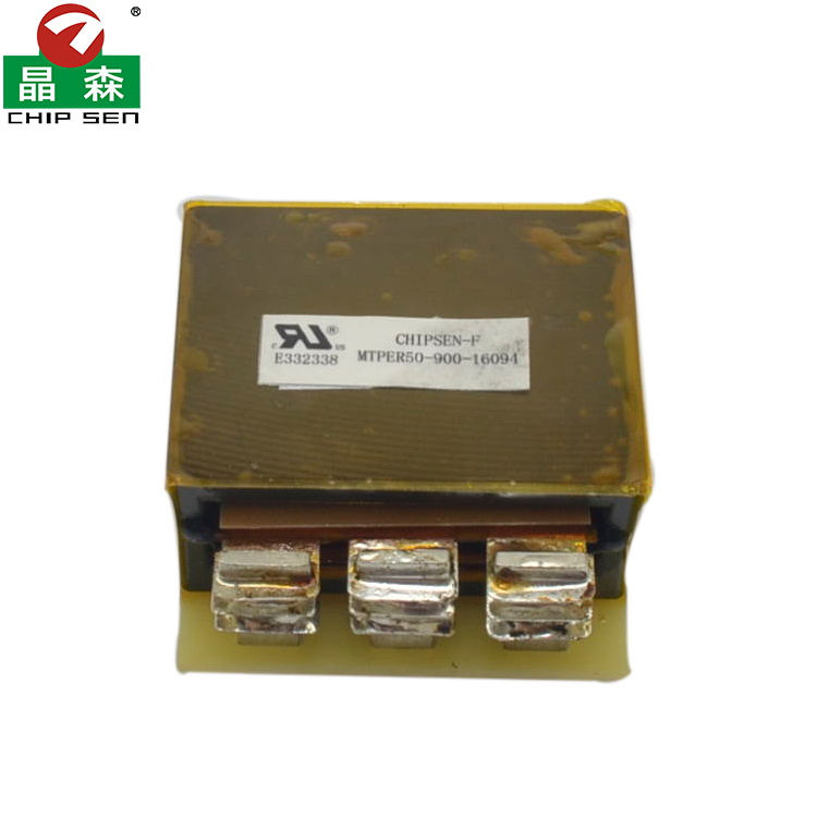
Low Leakage High Power EE65 High Frequency Transformer for Energy Systems

The values below are common international buyer inquiry references and starting points for engineering discussion. They are not fixed or guaranteed ratings for every EE65 transformer. Final electrical, magnetic, insulation, thermal, mechanical, environmental, and test requirements are confirmed through the approved specification, drawing, material system, converter conditions, and customer sample-validation process.

Industry Typical Application Typical Converter Input Condition Typical Output Requirement Typical Power Inquiry Common Switching Frequency Inquiry Key Parameters Evaluated by Buyers Available Customization
Energy storage systems Bidirectional isolated DC DC stage for PCS battery interface and auxiliary conversion High-frequency switched waveform derived from a 48 V to several-hundred-volt battery or DC link Isolated battery-side DC-link or auxiliary rail after rectification and filtering Approximately 300 W to 3000 W as an engineering discussion range Commonly 20 kHz to 200 kHz Flux balance magnetizing inductance leakage DCR AC resistance capacitance isolation efficiency contribution and hotspot temperature Turns ratio precision gap foil or litz winding symmetric construction shields busbars sensors insulation and cooling interface
Solar and wind power Isolated conversion for inverter DC links optimizers and renewable-energy power modules Switched waveform derived from a wide-range renewable-energy DC bus Customer-defined isolated DC link battery interface or auxiliary output Approximately 300 W to 3000 W as an inquiry reference Commonly 20 kHz to 200 kHz Wide-input flux density saturation margin leakage winding loss core loss insulation and thermal cycling Ferrite grade gap interleaving reinforced insulation low-capacitance winding leads busbars potting and thermal sensors
EV charging equipment Main or auxiliary isolated converter in onboard offboard and charging-station power modules High-frequency bridge or resonant waveform derived from a PFC bus battery bus or auxiliary supply Isolated charging bus control rail or service output after the converter power stage Approximately 300 W to 3000 W as a project starting point Commonly 30 kHz to 250 kHz Controlled leakage resonant behavior AC loss capacitance dielectric strength temperature rise and repeatability LLC-oriented leakage target interleaving foil litz shield reinforced insulation terminals busbars potting and mounting
Emergency power and UPS Battery converter inverter charger and high-power auxiliary stage Switched waveform derived from 24 V 48 V 72 V 96 V or a customer-defined DC link Isolated high-voltage or low-voltage rail according to the inverter architecture Approximately 300 W to 2500 W as an inquiry reference Commonly 20 kHz to 180 kHz Peak current saturation margin DCR leakage loss thermal balance startup stress and isolation Center tap parallel conductors copper foil litz precision gap shields thermal protection leads and mechanical reinforcement
Data center and AI power Isolated intermediate-bus converter server supply and high-density power module Switched waveform derived from a 48 V bus or high-voltage PFC link High-current isolated bus such as 12 V 24 V 48 V or a customer-defined rail Approximately 300 W to 2500 W as an engineering reference Commonly 50 kHz to 300 kHz Low leakage low AC and DC resistance capacitance core loss thermal path efficiency contribution and consistency Low-profile winding arrangement foil litz interleaving custom terminals busbars core fixing and tightened test limits
Industrial power supplies Main transformer for high-power isolated AC DC and DC DC converters Switched excitation derived from rectified mains a PFC link or a customer-defined DC bus Single dual or multiple isolated outputs after rectification and regulation Approximately 200 W to 2000 W as an inquiry reference Commonly 20 kHz to 250 kHz Volt-second balance primary inductance turns ratio leakage DCR AC loss insulation and temperature rise Ferrite material air gap conductor system winding sequence shields multiple outputs insulation terminals and cooling
Industrial battery charging and formation Isolated conversion for chargers cyclers formation racks AGVs and stationary battery systems Switched waveform derived from rectified mains or a low- or high-voltage battery bus Customer-specified charging voltage and current after rectification and control Approximately 300 W to 3000 W as a common discussion range Commonly 20 kHz to 180 kHz RMS and peak current flux balance copper loss leakage regulation isolation and thermal endurance Full-wave or center-tapped secondary foil litz parallel wire busbars thermal sensor insulation and impregnation
Welding plasma and industrial heating High-current isolated power conversion and pulsed-energy transfer Bridge push-pull or customer-defined high-frequency excitation with a documented duty profile High-current or high-voltage output according to the downstream rectifier and load Approximately 500 W to several kilowatts as an initial inquiry only Commonly 20 kHz to 150 kHz Pulse current saturation core loss proximity loss termination heating insulation and mechanical strength Heavy copper foil parallel windings busbars reinforced terminations gap core clamping insulation and forced-cooling interface
Telecom and communications power Isolated DC DC stage for rectifiers base stations network power and backup systems High-frequency switched waveform derived from a nominal 48 V bus or PFC link Isolated regulated intermediate or point-of-load bus Approximately 200 W to 2000 W as an inquiry reference Commonly 50 kHz to 300 kHz DCR AC resistance leakage capacitance EMI core loss thermal path and production consistency Foil or litz construction interleaving shields compact terminals busbars low-profile mounting and traceability

Important Note: The transformer is excited by a high-frequency switched or pulsed waveform generated by the converter. The DC-bus values in the matrix describe the source system and do not mean that unswitched DC can be applied directly to the transformer winding.

Major customizable parameters include converter topology, minimum and maximum bus voltage, winding waveform, switching frequency, duty cycle, continuous and peak power, turns ratio, magnetizing inductance, magnetizing current, air gap, peak and RMS winding current, flux-density limit, saturation margin, leakage-inductance target, DCR, AC winding resistance, interwinding capacitance, core material, copper foil, litz wire, parallel-wire construction, winding sequence, electrostatic shield, insulation system, dielectric test level, creepage, clearance, terminals, leads, copper tabs, busbars, mounting, impregnation, potting, temperature sensing, cooling method, temperature-rise limit, marking, and production-test criteria.

Product Overview

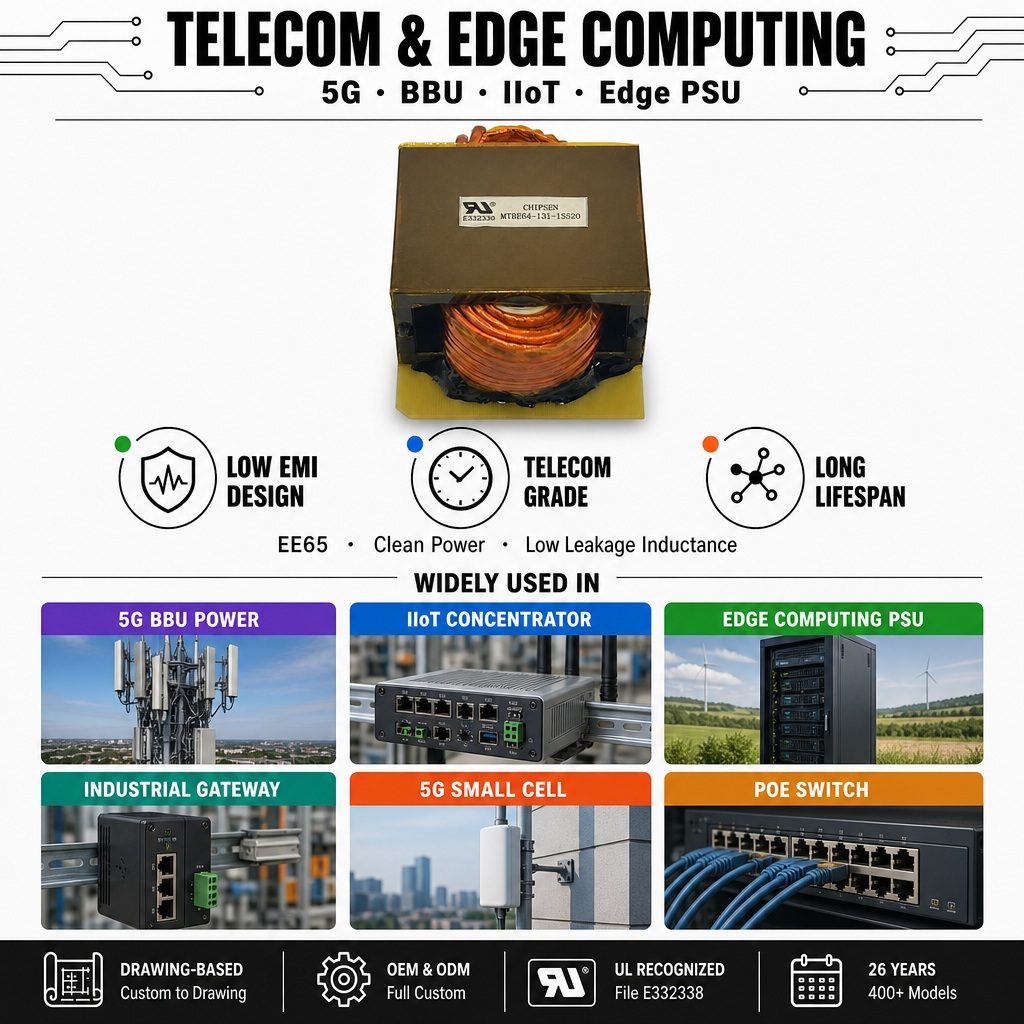
The EE65 is a large ferrite-core high-frequency transformer platform intended for isolated power conversion in energy-storage systems, solar and wind equipment, EV chargers, industrial UPS systems, data-center power supplies, battery chargers, industrial converters, and other demanding power-electronics applications.

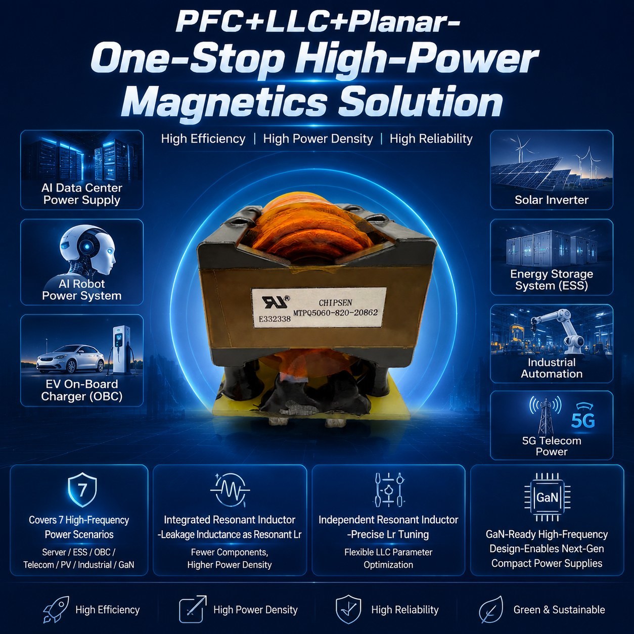
The product design focuses on two key objectives: extremely low leakage inductance and outstanding heat-dissipation efficiency. These statements are treated as development objectives rather than universal guaranteed values. The exact leakage limit, test frequency, winding condition, cooling environment, temperature-rise limit, and acceptance method must be defined in the approved specification.

Design Note: EE65 identifies an approximate core-size platform and does not define one fixed voltage, current, power, frequency, inductance, leakage, isolation, or thermal rating. Final capability depends on multiple factors including converter topology, switching waveform, bus voltage, frequency, ferrite grade, conductor design, insulation system, and cooling conditions.

Construction Details
Construction Item EE65 Customization Reference
Magnetic platform EE65 ferrite-core platform or an approved equivalent selected according to waveform frequency flux density core loss window utilization and thermal requirements
Ferrite material Power ferrite grade selected according to switching frequency waveform temperature core-loss target and availability
Core gap Ungapped distributed-gap or precision-gapped construction developed around magnetizing inductance peak current stored energy and saturation margin
Bobbin or winding former Standard bobbin split bobbin custom former or bobbinless construction selected according to winding window insulation and mechanical needs
Primary winding Single split parallel center-tapped or multi-section primary according to topology current waveform and leakage target
Secondary winding Single dual center-tapped parallel multiple-output or high-current low-voltage secondary according to rectification and regulation requirements
Winding conductor Round enameled copper wire parallel multi-strand wire litz wire copper foil flat copper or a combined conductor system
Winding arrangement Layered interleaved sandwich sectional or separated winding structure developed around leakage capacitance isolation and thermal priorities
Insulation system Film tape barriers sleeving margin construction spacers and lead insulation selected according to working voltage dielectric test and thermal class
Electrostatic shielding Optional primary-to-secondary shield with a defined grounding termination where common-mode-noise control is required
External magnetic shielding Optional flux band or approved magnetic shielding where stray-field performance requires additional control
Terminations PCB pins flying leads copper tabs lugs terminals connectors or busbars selected according to current assembly clearance and serviceability
Core retention Tape adhesive clamp bracket or customer-approved fixture developed for gap stability vibration transport and production handling
Impregnation and potting Varnish partial potting full encapsulation or thermally conductive compound considered according to insulation vibration moisture and thermal requirements
Cooling interface Natural convection forced air cold plate thermal pad chassis conduction or customer-defined cooling arrangement
Temperature monitoring Optional thermostat thermistor RTD or another sensor positioned according to the approved thermal-validation plan
Marking and traceability Custom model winding identification polarity marks date code lot code test status and customer label under the approved control plan
Key Product Characteristics
Low Leakage Inductance Development

Leakage inductance can be reduced through winding interleaving, shorter current paths, controlled layer placement, close magnetic coupling, consistent winding tension, and optimized termination geometry.

Balanced Leakage Capacitance and Isolation

Winding sequence, spacing, shielding, barriers, and sectional construction are selected according to switching speed, common-mode-noise behavior, isolation level, and safety requirements.

Heat Dissipation Oriented Design

Conductor cross-section, winding fill, layer distribution, termination area, insulation thermal conductivity, core contact, and airflow path are reviewed as one thermal system.

High Current Conductor Options

Copper foil, litz wire, flat copper, parallel conductors, multi-strand wire, copper tabs, and busbar terminations manage RMS current, DCR, skin effect, proximity loss, and termination temperature.

Core and Copper Loss Control

Ferrite grade, flux swing, frequency, waveform, gap, conductor strand size, foil thickness, and winding arrangement all affect total loss optimization.

High Power Density Potential

The EE65 platform provides substantial magnetic cross-section and winding window for medium- and high-power conversion projects with optimized thermal management.

Applications
  • Energy-storage PCS and bidirectional battery converters
  • Solar inverters and renewable-energy power modules
  • Wind-power converter systems
  • EV charging equipment and isolated charger stages
  • Industrial UPS and emergency-power converters
  • Data-center server and AI power systems
  • High-density isolated DC DC converters
  • Industrial high-power switched-mode power supplies
  • Battery chargers formation racks and test equipment
  • Telecom rectifiers and communications power systems
  • Industrial motor drives and robotics
  • Welding plasma and industrial heating equipment
  • Railway marine and transportation power electronics
  • Isolated gate-drive and auxiliary power systems
  • Full-bridge half-bridge push-pull forward and resonant converters
  • Customer-specific high-frequency isolation and energy-transfer systems

Application Note: Suitability for any application must be confirmed according to the actual circuit topology, switching waveform, electrical stress, insulation coordination, thermal environment, mechanical installation, applicable standards, and customer validation conditions.

Quality Control & Testing

Our comprehensive quality control process ensures consistent performance and reliability:

Incoming Material Inspection

Ferrite cores, bobbins, winding formers, copper materials, insulation components, terminals, and all materials are inspected according to approved control plans.

Design Review

Comprehensive engineering review of topology, electrical parameters, thermal performance, insulation requirements, and production tolerances.

In-Process Control

Process controls including turns counting, winding direction, insulation placement, gap control, and workmanship inspection throughout manufacturing.

Electrical Testing

Tests include magnetizing inductance, leakage inductance, turns ratio, polarity, DCR, dielectric strength, insulation resistance, and application-specific validation.

Why Choose Chipsen
Application Specific Customization

Development around topology, voltage range, frequency, power profile, current waveform, and operating environment requirements.

Low Leakage Engineering Support

Expert review of winding interleaving, layer arrangement, coupling area, and termination geometry for controlled leakage targets.

Thermal Design Collaboration

Comprehensive evaluation of core loss, copper loss, hotspots, cooling methods, and enclosure conditions before production approval.

OEM and ODM Support

Support for new designs, approved-specification builds, drawing-based manufacturing, and application-based engineering review.

Send your message to this supplier
Send Now

Energy Storage 1500W PSFB EE65 Transformer 400V to 48V Low Leakage

Ask Latest Price
Watch Video
Model Number :
EE65
Installation :
SMD LEAD
MOQ :
1K
Delivery Time :
7-14 work days (Negotiable)
Frequency Range :
200 kHz to 700 kHz
Leakage Inductance :
< 0.2% to 0.5% of Primary Inductance
Contact Supplier
video
Energy Storage 1500W PSFB EE65 Transformer 400V to 48V Low Leakage

Dongguan Chipsen Electronics Technology Co., Ltd.

Verified Supplier
1 Years
guangdong, dongguan
Since 2007
Business Type :
Manufacturer
Total Annual :
28820000-29820000
Employee Number :
400~450
Certification Level :
Verified Supplier
Contact Supplier
Submit Requirement