Shell and Tube Heat Exchanger Tube Bundle, Fixed / U-Tube / Floating Head, Design Pressure Up to 35 MPa | Per TEMA / ASME VIII-1 / GB/T 151
Product Overview
The tube bundle is the removable or fixed core assembly within a shell and tube heat exchanger, comprising tubes, tube sheets, baffles, tie rods, and spacers. This assembly is the primary heat transfer interface between two fluid streams - one flowing inside the tubes (tube side) and the other across the external tube surfaces (shell side).
The tube bundle is designed and manufactured per TEMA Class C (commercial), B (chemical), or R (refinery), ASME Section VIII Division 1 or Division 2, and GB/T 151 for domestic applications. This product is supplied as a replacement bundle, a spare bundle, or as part of a new heat exchanger assembly.
Tube Bundle Types - Structural Classification
Fixed Tube Sheet (TEMA L / M / N)
- Tubes are expanded or welded into tube sheets at both ends
- Shell and tube sheets are integrally welded or bolted to the shell
- Thermal expansion is accommodated by an expansion joint installed on the shell when ΔT between tube and shell exceeds the allowable for the material combination
- Applicable for: Clean shell-side fluids, temperature differential ≤ 60°C (carbon steel) / ≤ 40°C (stainless steel) without expansion joint; non-fouling services
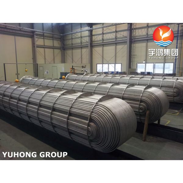
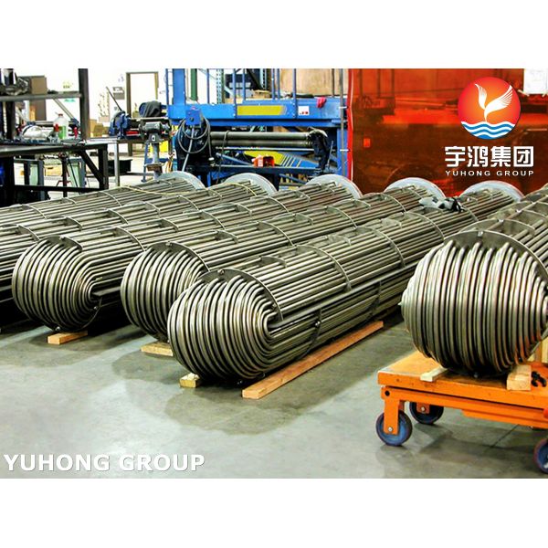
U-Tube Bundle (TEMA U)
- Tubes are bent into a U-shape, with both ends fixed to a single tube sheet
- Each tube is free to expand independently, accommodating large temperature differentials without requiring a shell expansion joint
- Applicable for: High thermal differential (ΔT up to 200°C), high-pressure gas service, hydrogen service, thermal shock conditions
- Limitation: Individual tube cleaning is not possible - only chemical cleaning; U-bend radius ≥ 2* tube OD per TEMA RCB-4.52
Floating Head Bundle (TEMA P / S / T / W)
- One tube sheet is fixed (stationary) and the other is floating, allowing the bundle to expand independently from the shell
- Rear head is removable, enabling bundle extraction for mechanical cleaning
- Applicable for: Severe fouling services where mechanical cleaning is required, large ΔT, high shell-side fouling factor (> 0.0005 m²*K/W per TEMA table)
- Limitation: Higher cost, more flange joints, greater tube sheet thickness requirement
Core Components - Geometric and Functional Specifications
Tubes
| Parameter |
Range |
Standard / Note |
| Tube OD |
12.7mm - 50.8mm (1/2" to 2") |
Smaller OD for higher pressure; larger OD for fouling service |
| Tube wall thickness |
0.9mm - 5.0mm |
Selected per ASME VIII-1 UG-27 for internal pressure; gauge thickness per ASTM B730 |
| Tube length (straight) |
1.5m - 12.0m |
Standard TEMA lengths: 2.44m, 4.88m, 6.10m, 9.75m |
| Tube pitch |
1.25* - 2.0* tube OD |
Triangular pitch (30°) for higher heat transfer; square pitch (90°) for mechanical cleaning access |
| Tube arrangement |
Triangular (30°/60°) / Square (90°/45°) |
Triangular gives highest surface area per shell cross-section; square allows rod or brush cleaning access to shell side |
Tube Sheets
| Parameter |
Range / Value |
Standard / Note |
| Thickness |
20mm - 300mm |
Per TEMA RCB-4.3 - selected to withstand tube-to-tubesheet joint loads and shell/tube side pressure independently |
| Hole diameter tolerance |
H11 (e.g., Ø25.2mm +0.13/0) |
Per ISO 286 / TEMA standard |
| Hole finish |
Ra ≤ 1.6μm (expanded) / Ra ≤ 3.2μm (welded) |
Expansion requires finer finish to achieve pull-out strength |
| Ligament (bridge between holes) |
Minimum 0.8* hole diameter |
Per ASME VIII-1 Appendix A - to prevent tube sheet deformation |
| Tube sheet material |
CS / SS clad / alloy / solid |
Selected per tube-side and shell-side fluid compatibility |
Baffles and Support Plates
| Parameter |
Range / Value |
Standard / Note |
| Baffle type |
Segmental (20-35% cut) / Double segmental / Helical / No-baffle (full supports only) |
Segmental cut percentage selected per TEMA for cross-flow velocity |
| Baffle spacing |
0.2* - 1.0* shell ID |
Determined by unsupported tube length limit and required cross-flow velocity |
| Maximum unsupported tube length |
CS: ≤ 36* tube OD; SS: ≤ 30* tube OD |
Per TEMA RCB-4.2 to prevent tube vibration and sag |
| Baffle thickness |
3.0mm - 16mm |
Based on shell side pressure differential and support span |
| Tie rod diameter |
M8 - M24 (or equivalent imperial) |
Minimum 4 rods per bundle; diameter selected per TEMA RCB-4.6 to support bundle weight |
Tube-to-Tubesheet Joint Types
| Joint Type |
Method |
Pull-Out Strength (Min) |
Applicable Service |
Inspection Method |
| Expanded only |
Hydraulic expansion at 160-220 MPa, hold 5-8s |
≥ 20 MPa (CS) / ≥ 25 MPa (SS) |
Non-toxic, non-cyclic service; clean fluids |
Hydrostatic test + pull-out test on first article |
| Welded only (seal weld) |
GTAW (TIG) fillet weld leg 1.5-2.0mm |
N/A (mechanical retention from weld only) |
High-pressure gas, hydrogen service |
100% PT per ASME VIII-1 UW-51 |
| Weld + expand (combined) |
Seal weld + hydraulic expansion at 160-200 MPa |
≥ 25 MPa |
Cyclic thermal service (> 500 cycles/year), high pressure, toxic fluids |
100% PT + hydrotest + pull-out test on first article |
Material Selection - Per Service Condition
Tube Material Options
| Material |
Spec |
Temp Range |
Chloride Limit |
Application Notes |
| Carbon steel SA-179 / SA-106 Gr.B |
ASTM A179 / A106 |
-20°C to +425°C |
Not applicable |
Water, oil, steam, clean hydrocarbons |
| Carbon steel 20# |
GB 8163 |
-20°C to +425°C |
Not applicable |
Domestic standard equivalent to SA-106 |
| Stainless 304L / 304 |
ASTM A213 TP304L |
-196°C to +600°C |
≤ 200ppm |
Mildly corrosive fluids, clean steam, food grade |
| Stainless 316L / 316 |
ASTM A213 TP316L |
-196°C to +500°C |
≤ 200ppm |
Organic acids, salt solutions, chloride-containing hydrocarbons |
| Duplex 2205 |
ASTM A789 S32205 |
-40°C to +280°C |
≤ 300ppm at 80°C |
Offshore, seawater, chlorides, CO₂/H₂S service |
| Titanium Gr.2 |
ASTM B338 |
-40°C to +230°C |
Up to 20,000ppm |
Seawater, brine, high-chloride environments |
| Alloy 800H / 825 / 625 |
ASTM B163 |
-196°C to +600°C |
Up to 500ppm |
High-temperature corrosive service, sour gas, amine units |
Tube Sheet Material (Clad or Solid)
- Carbon steel SA-516 Gr.70 - for non-corrosive tube-side fluids
- Stainless clad (304L/316L over CS) - for corrosive tube-side fluids with high pressure (cladding thickness min. 3mm per ASME VIII-1 UW-13)
- Solid stainless 304L / 316L - for fully corrosive service
- Duplex / Titanium - for offshore and seawater service
- Alloy overlay (Inconel 625 weld overlay, min. 3mm) - for severe sour or chloride service
Operational Parameters - Tube Bundle Service Rating
| Parameter |
Range |
Notes |
| Tube-side design pressure |
Vacuum (-0.1 MPa) to 35 MPa |
Higher pressure requires seamless tube and heavy wall tube sheet |
| Shell-side design pressure |
Vacuum (-0.1 MPa) to 10 MPa (standard) |
Dependent on shell construction and flange rating |
| Tube-side design temperature |
-196°C to +600°C |
Material dependent; cryogenic service requires impact testing per ASME VIII-1 UG-84 |
| Shell-side design temperature |
-40°C to +450°C |
Dependent on shell material and gasket type |
| Tube-side fluid |
Liquids, gases, condensing vapors, two-phase mixtures |
Compatible with tube material |
| Shell-side fluid |
Liquids, gases, condensing vapors, boiling fluids |
Compatible with shell material (tube OD material if direct contact) |
| Maximum tube-side velocity (liquid) |
2.5 - 4.5 m/s |
Carbon steel max 3.0 m/s; titanium max 4.5 m/s per TEMA erosion velocity guideline |
| Maximum tube-side velocity (gas) |
15 - 30 m/s |
Limited by vibration and pressure drop |
| Tube-side Reynolds number target |
≥ 10,000 (turbulent) for clean service |
Lower values require increased surface area or lower thermal performance |
Replacement Bundle - Key Considerations
When ordering a replacement bundle, provide:
- Original bundle drawing number (if available)
- TEMA type (L / M / N / U / P / S / T / W)
- Shell ID, tube OD and wall thickness, tube length, tube pitch, tube arrangement
- Tube sheet thickness and material
- Baffle type, baffle spacing, number of baffles
- Tube-to-tubesheet joint type (expanded / welded / combined)
- Design pressure and temperature (tube and shell sides)
- Fluid composition (tube and shell sides) - to verify material compatibility
- Nozzle orientation (if applicable) - for inlet/outlet alignment with existing piping
- Required corrosion allowance (tube and tube sheet) - for remaining life extension
Selection Checklist - New or Replacement Tube Bundle
- Define TEMA type based on thermal expansion and cleaning requirements:
- Fixed tubesheet (L/M/N) - for clean shell side, ΔT ≤ 60°C
- U-tube (U) - for large ΔT, hydrogen service, high pressure
- Floating head (P/S/T/W) - for severe fouling, mechanical cleaning
- Select tube material based on tube-side fluid corrosivity and temperature.
- Select tube sheet material based on shell-side and tube-side fluid compatibility (clad or solid).
- Select tube OD, wall thickness, pitch, and arrangement:
- Triangular pitch for max surface area
- Square pitch for mechanical cleaning access (rod/brush)
- Specify baffle type and spacing - based on shell-side allowable ΔP and vibration criteria.
- Specify joint type - expanded (low cost), welded (gas/hydrogen), or combined (cyclic service).
- Provide design pressure and temperature for hydrotest and material grade selection.
- Specify whether a spare bundle is required for service rotation (reduce downtime during cleaning).
Design Limitation Statement - Tube Bundle
The tube bundle as a standalone product is not applicable for:
- Direct installation without matching shell geometry - tube OD, length, and tube sheet thickness must match shell dimensions
- Extreme vacuum service (< 1 kPa absolute) without external support rings or tube sheet bracing - requires additional stiffening per ASME VIII-1 UG-29
- Service with tube-side solids content > 2% by weight without upstream filtration - erosion and tube wall thinning will occur
- Severe thermal cycling (> 2,000 cycles/year) with expanded-only joints - combined weld + expand joint required