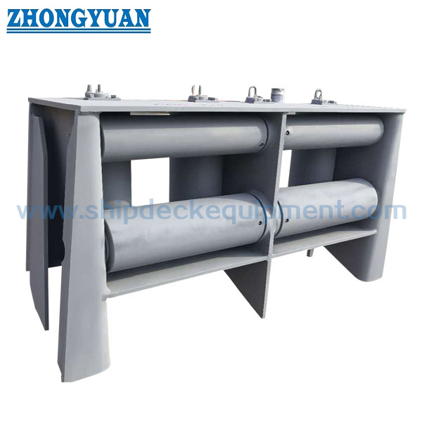
Seven-Roller Universal Fairlead with Upper Roller | Ship Mooring and Towing (ISO 13733 Type 7R)
Product Overview
The ISO 13733 Type 7R universal fairlead is a deck-mounted seven-roller rope guide with two rope-passing openings and an upper roller arrangement. It is used to guide ship mooring or towing lines where the rope lead includes horizontal and vertical direction changes. Rotating roller contact reduces sliding friction at the guide point and helps keep the line within a controlled passage.
The nominal size is based on the outside diameter of the main roller. For nominal sizes 300 and 400, the A / B / C suffix distinguishes different SWL levels while the principal roller dimensions remain the same. Final selection should be coordinated with rope type and diameter, required SWL, line lead angle, standard load direction, roller rotation, shaft and bearing maintenance, deck reinforcement, welding details, and class inspection scope.
Quick Specifications
Main Technical Parameters
|
Nominal size Dn |
B x H |
D1 |
D2 |
h |
h1 |
h2 |
b |
b1 |
b2 |
b3 |
b4 |
w |
c |
|||||||||
| 140 | 195 x 150 | 139,8 | 114,3 | 277 | 130 | 480 | 335 | 850 | 1 000 | 1 160 | 140 | 260 | 150 | |||||||||
| 160 | 200 x 150 | 165,2 | 114,3 | 290 | 145 | 515 | 365 | 935 | 1 100 | 1 286 | 140 | 310 | 175 | |||||||||
| 180 | 200 x 150 | 190,7 | 139,8 | 315 | 155 | 560 | 391 | 1 011 | 1 200 | 1 400 | 140 | 360 | 200 | |||||||||
| 200 | 200 x 150 | 216,3 | 139,8 | 328 | 170 | 590 | 416 | 1 091 | 1 320 | 1 550 | 140 | 410 | 225 | |||||||||
| 250 | 250 x 200 | 267,4 | 165,2 | 416 | 195 | 715 | 517 | 1 342 | 1 580 | 1 820 | 180 | 520 | 280 | |||||||||
| 300A | 300 x 250 | 318,5 | 216,3 | 517 | 220 | 870 | 618 | 1 598 | 1 840 | 2 150 | 200 | 620 | 330 | |||||||||
| 300B | 300 x 250 | 318,5 | 216,3 | 517 | 220 | 870 | 618 | 1 598 | 1 840 | 2 150 | 200 | 620 | 330 | |||||||||
| 400A | 350 x 250 | 406,4 | 216,3 | 561 | 265 | 960 | 756 | 1 966 | 2 250 | 2 550 | 200 | 795 | 420 | |||||||||
| 400B | 350 x 250 | 406,4 | 216,3 | 561 | 265 | 960 | 756 | 1 966 | 2 250 | 2 550 | 200 | 795 | 420 | |||||||||
| 400C | 350 x 250 | 406,4 | 216,3 | 561 | 265 | 960 | 756 | 1 966 | 2 250 | 2 550 | 200 | 795 | 420 | |||||||||
|
Nominal size Dn |
e |
w1 |
w2 |
T |
T1 |
T2 |
T3 |
T4 |
f |
Welding leg length | SWL |
Calculated weight (kg) |
||||||||||
| z1 | z2 | (kN) | (ton) | |||||||||||||||||||
| 140 | 70 | 30 | 100 | 12 | 12 | 18 | 12 | 12 | 6 | 9 | 7 | 137 | 14 | 256 | ||||||||
| 160 | 83 | 40 | 100 | 14 | 14 | 20 | 14 | 14 | 6 | 10 | 7 | 196 | 20 | 357 | ||||||||
| 180 | 95 | 40 | 100 | 16 | 16 | 28 | 16 | 16 | 8 | 11 | 9 | 245 | 25 | 481 | ||||||||
| 200 | 108 | 50 | 100 | 18 | 18 | 28 | 18 | 18 | 8 | 13 | 9 | 314 | 32 | 629 | ||||||||
| 250 | 133 | 65 | 200 | 22 | 26 | 36 | 20 | 20 | 10 | 18 | 10 | 510 | 52 | 1307 | ||||||||
| 300A | 159 | 80 | 200 | 24 | 28 | 46 | 24 | 22 | 10 | 20 | 10 | 687 | 70 | 2013 | ||||||||
| 300B | 159 | 80 | 200 | 26 | 30 | 48 | 24 | 22 | 10 | 21 | 10 | 736 | 75 | 2154 | ||||||||
| 400A | 203 | 100 | 200 | 26 | 30 | 40 | 32 | 28 | 10 | 21 | 10 | 981 | 100 | 2924 | ||||||||
| 400B | 203 | 100 | 200 | 28 | 32 | 52 | 32 | 28 | 10 | 22 | 10 | 1 256 | 128 | 3344 | ||||||||
| 400C | 203 | 100 | 200 | 30 | 34 | 54 | 32 | 28 | 10 | 24 | 10 | 1 373 | 140 | 3591 | ||||||||
Selection & Inquiry Guide
Step 1: Confirm ISO 13733 Type 7R and the required nominal size according to the vessel mooring or towing arrangement.
Step 2: Provide rope type, rope diameter, rope MBL, required fairlead SWL, expected horizontal and vertical lead directions, and the operating line path.
Step 3: For 300A / 300B and 400A / 400B / 400C, select the suffix according to the required SWL; do not select only by roller diameter.
Step 4: Confirm installation position, available deck space, foundation and deck reinforcement, welding interface, nearby equipment clearance, and roller maintenance access.
Step 5: Confirm frame, roller, shaft, bearing or bush material requirements; lubrication arrangement; surface treatment; and corrosion-protection system.
Step 6: Confirm quantity, class society requirement, material traceability, inspection and test scope, delivery destination, required delivery time, and provide the vessel drawing or reference photo if available.
Structure
Seven-roller assembly | Two rope-passing openings | Upper roller | Main guiding rollers | Steel support frame | Roller shafts | Bearings or bushes | Deck-welded base | Lubrication points | Specified surface treatment
Mooring, Towing & Engineering Advantages
Custom Attributes
How It Works
Mooring or towing line approaches the fairlead → The line enters the selected rope-passing opening → Main and upper rollers rotate as the lead direction changes → Rolling contact guides the line and reduces sliding friction → Fairlead reactions transfer through the welded frame into the reinforced deck structure
Applications
Ship mooring stations | Ship towing stations | Tugboats | Workboats | Cargo vessels | Tankers | Offshore support vessels | Newbuilding projects | Replacement of standard universal fairleads
Certifications & Advantages
Certificates and inspection documentation can be arranged according to project requirement, material traceability, test scope, and class approval procedure. The required certificate level and witness points should be confirmed before quotation.
Certification: CCS, NK, BV, ABS, DNV, LR, KR, IRS, RS, RINA, CRS, Makers Test Certificate.
Drawing & Photos


FAQ
Q1: What is the difference between an ISO 13733 Type 7R universal fairlead and a fixed mooring chock?
A1: Type 7R uses seven rotating rollers and two defined rope-passing openings to guide a line through horizontal and vertical lead changes. A fixed chock uses a stationary rope-contact surface. The correct product should follow the vessel mooring or towing arrangement.
Q2: How should 300A / 300B or 400A / 400B / 400C be selected?
A2: Models with the same nominal roller size have the same principal roller diameters but different SWL ratings and calculated weights. Select the suffix according to the required fairlead SWL, standard load case, deck structure, and approved vessel drawing.
Q3: Can both rope-passing openings be loaded at the full listed SWL at the same time?
A3: Simultaneous loading should not be assumed from the model table alone. The operating line arrangement, load directions, combined reactions, deck reinforcement, and approval requirement must be confirmed from the official standard drawing and the vessel-specific engineering calculation.