Four-Roller Fairlead for Engineering Vessel | CB 3015 Type A for Towing and Mooring Lines
Product Overview
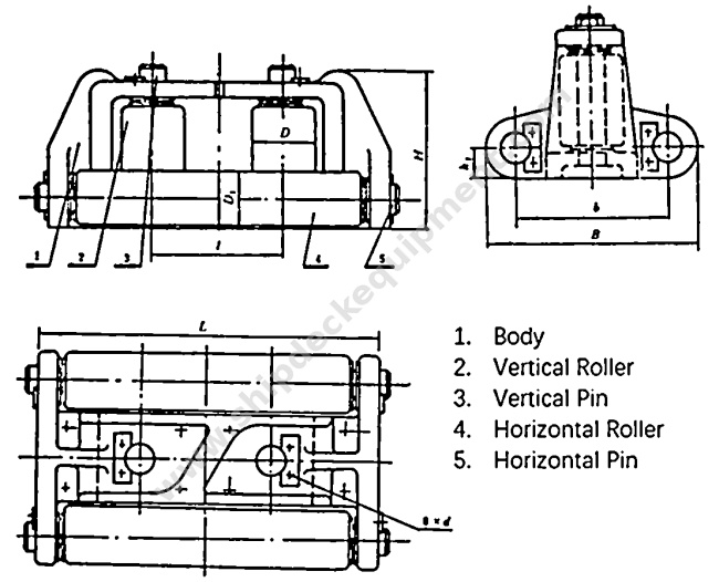
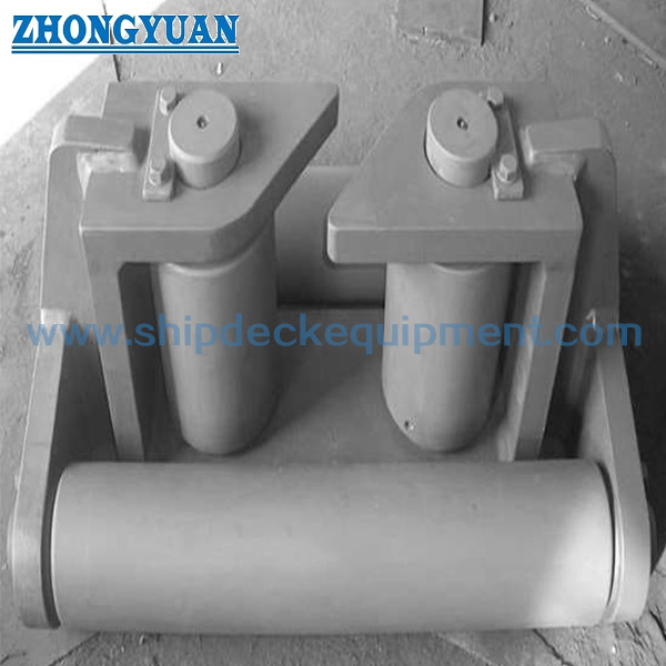
The CB 3015 Type A engineering vessel fairlead is a roller-guidance assembly used to control the path of steel wire rope or another project-specified line at an engineering vessel rope-lead position. Its four-roller arrangement uses two vertical rollers and two horizontal rollers to form a guided opening, helping the line change direction while reducing sliding contact against fixed steel edges.
The size range is based on vertical roller diameter D from 100 to 300 mm, with reference steel wire rope diameters from 19.5 to 56 mm. Selection should be coordinated with the vessel towing or mooring arrangement, line construction, lead angle, project design load, mounting foundation, roller material, shaft arrangement, lubrication method, coating system, and inspection scope. The official standard number is CB 3015-1983, also commonly shown in legacy documents as CB* 3015-83.
Quick Specifications
Main Technical Parameters
| Roller Dia. D |
Horizontal Roller Dia. D1 |
Applicable Steel Wire Rope Dia. Φ |
L | B | H | b | h1 | h2 | l | d |
| 100 | 85 | 19.5 | 540 | 340 | 240 | 250 | 220 | 50 | 200 | 22 |
| 150 | 120 | 26 | 760 | 460 | 340 | 340 | 320 | 65 | 290 | 26 |
| 200 | 150 | 37.5 | 980 | 580 | 430 | 430 | 410 | 80 | 380 | 32 |
| 250 | 200 | 176 | 1220 | 740 | 520 | 540 | 500 | 110 | 480 | 39 |
| 300 | 250 | 370 | 1460 | 900 | 620 | 650 | 590 | 135 | 580 | 39 |
Selection & Inquiry Guide
Step 1: Confirm CB 3015-1983 Type A and select model D100, D150, D200, D250, or D300 according to the vessel drawing and required roller opening.
Step 2: Confirm steel wire rope diameter, rope construction, minimum bending requirement, working line direction, and expected lead angles. The reference rope diameter must not be treated as the product SWL or MBL.
Step 3: Confirm installation position, available space, mounting-hole arrangement, foundation or local reinforcement, and whether the fairlead is for a newbuilding or replacement project.
Step 4: Confirm the component material split for frame, rollers, shafts, bushes or bearings, together with lubrication and maintenance requirements.
Step 5: Confirm surface treatment, final coating, material traceability, class society involvement, inspection witnessing, and certificate scope before quotation.
Step 6: Provide quantity, vessel type, application, drawing or photos, delivery destination, required delivery time, and any replacement interchangeability requirement.
Structure
Two vertical rollers | Two horizontal rollers | Roller shafts | Side and support frame | Mounting-hole interface | Guided rope opening | Protective surface treatment
Roller Guidance, Installation & Quality Advantages
Custom Attributes
How It Works
Towing or mooring line approaches the fairlead → Line contacts the required vertical and/or horizontal roller → Rollers rotate as the line changes direction → Contact reaction passes through shafts and frame → Load is transferred into the vessel mounting foundation
Applications
Dredgers | Crane vessels | Pile-driving vessels | Engineering barges | Construction workboats | Towing-line guidance positions | Mooring-line guidance positions | Newbuilding and replacement projects
Certifications & Advantages
Certificates and inspection can be arranged according to project requirement, material traceability, agreed test scope, and classification society approval procedure.
Certification: CCS, NK, BV, ABS, DNV, LR, KR, IRS, RS, RINA, CRS, Makers Test Certificate.
Drawing & Photos


FAQ
Q1: How should the correct CB 3015 Type A size be selected?
A1: Start with the vessel drawing, roller diameter D, applicable wire rope diameter, required clear opening, line direction, and available installation space. Then confirm rope construction, lead angles, project design load, and foundation arrangement before final approval.
Q2: Does the applicable wire rope diameter represent the fairlead SWL or MBL?
A2: No. The table gives a reference rope diameter and principal dimensions. It does not provide a verified product SWL, MBL, test load, or breaking load. These values must be established from the project design basis, structural calculation, vessel foundation, and approval requirement.
Q3: What must be confirmed before manufacture and certification?
A3: Confirm the standard and type, model D, rope data, frame and roller materials, shaft and bush or bearing details, lubrication, surface treatment, mounting foundation, quantity, certificate scope, class society requirement, destination, and delivery schedule.