Bolted Marine Side Scuttle with Storm Cover | ISO 1751 Type B Medium Series
Product Overview
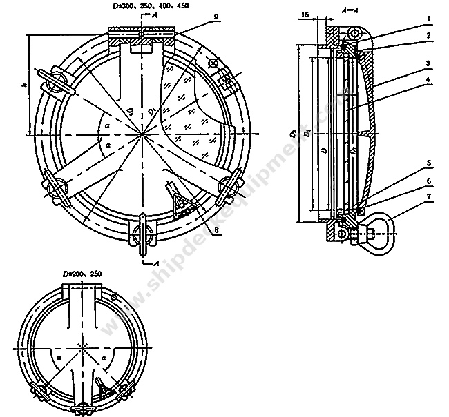
The bolted marine side scuttle with storm cover is an opening, medium-type Type B side scuttle for installation in a vessel shell plate or bulkhead. It belongs to regular series N and is intended for non-fire-rated construction. The main frame is secured to the ship structure by mounting bolts, while the opening glassholder and metal deadlight, also called a storm cover, use a common hinge arrangement. Swing bolts and nuts provide the closing force for the glassholder and deadlight.
In normal service, the glazed opening provides daylight and external visibility. When the deadlight is closed and correctly seated against its gasket, it provides an additional protective closure for weather exposure, sea impact, damage-control conditions, or operating procedures defined by the vessel. Correct selection depends not only on nominal diameter, but also on installation position, design pressure, shell or bulkhead thickness, wall opening, bolt pattern, glass and gasket specification, opening direction, material compatibility, test scope, and classification approval.
Quick Specifications
Main Technical Parameters
| Nominal Diameter D |
D1 | D2 | D3 | D4 | D5 | h | t | a | Fasteners Number for Glass Holder |
Fasteners Number for Storm Cover |
Mounting Bolts Size |
Mounting Bolts Number |
Wall Opening Size |
Weight kg |
| 200 | 245 | 204 | 250 | 350 | 310 | 155 | 8 | 45° | 3 | 2 | M12 | 8 | 253 | 14.23 |
| 250 | 295 | 254 | 305 | 400 | 364 | 182 | 42° | M16 | 308 | 17.16 | ||||
| 300 | 350 | 304 | 360 | 450 | 414 | 207 | 10 | 31° | 3 | 12 | 363 | 22.74 | ||
| 350 | 400 | 354 | 410 | 500 | 464 | 232 | 12 | 32° | 413 | 26.93 | ||||
| 400 | 450 | 404 | 460 | 550 | 514 | 257 | 31° | M18 | 463 | 31.07 | ||||
| 450 | 500 | 454 | 510 | 600 | 564 | 282 | 15 | 4 | M20 | 513 | 36.83 |
Selection & Inquiry Guide
Step 1: Confirm the governing standard and designation: ISO 1751:2012 regular series N, Type B medium type, opening bolted model with deadlight; state left-hand or right-hand opening and mark the viewing direction on the drawing.
Step 2: Select nominal diameter and provide the required clear opening, wall opening, shell or bulkhead thickness, mounting-bolt circle, bolt-hole diameter, frame depth, available hinge clearance, and maintenance access.
Step 3: Provide the exact installation position: vessel type, deck or compartment, distance above the assigned load line, exposure to sea or weather, internal or external opening direction, and applicable design pressure or class rule.
Step 4: Confirm the complete material system: main frame, glassholder, deadlight, hinges, swing bolts, mounting bolts, glass retaining parts, gasket, and finish. Mixed materials require a corrosion and galvanic-compatibility review.
Step 5: Confirm the safety-glass standard, pane thickness, gasket specification, hydrostatic / hose test pressure and holding time, mechanical-strength requirement, marking, material traceability, class witnessing, and certificate scope.
Step 6: Provide quantity, approved or reference drawing, replacement photos if applicable, required delivery time, packing requirement, delivery destination, and the classification society involved in the vessel project.
Structure
Bolted main frame | Opening glassholder | Thermally toughened safety glass | Glass retaining frame | Common hinge arrangement | Metal deadlight / storm cover | Swing-bolt and nut fasteners | Sealing gaskets | Mounting bolts
Watertightness, Installation and Quality Advantages
Custom Attributes
How It Works
Open the swing-bolt fasteners → Swing the deadlight and glassholder clear on their hinges → Use the glazed opening for daylight and visibility → Return the glassholder squarely onto its gasket and tighten evenly → Close and secure the deadlight when additional protective closure is required → Inspect gasket contact and locking condition
Applications
Ocean-going cargo vessels | Inland-waterway vessels | Workboats and service vessels | Naval or government vessels subject to project approval | Accommodation and service-space side openings | Newbuilding, conversion, and replacement projects
Certifications & Advantages
Material certificates, maker documentation, inspection reports, and classification certificates can be arranged according to project requirement, approved drawings, testing scope, and the relevant class approval procedure. Availability and witness scope must be confirmed before quotation and are not implied as standard delivery for every order.
Certification: CCS, NK, BV, ABS, DNV, LR, KR, IRS, RS, RINA, CRS, Makers Test Certificate.
Drawing & Photos


FAQ
Q1: Is ISO 1751 Type B the same as a B-class fire-resistant side scuttle?
A1: No. Type B in this page means the medium mechanical type within the ISO 1751 side-scuttle classification. A B-class fire-resistant side scuttle is a separate fire-tested assembly for a B-class division and requires an approved standard such as ISO 5797.
Q2: Can the same bolted side scuttle be installed at any position on the ship side?
A2: No. Permitted position and required strength depend on the vessel, deck level, height above load line, exposure, design pressure, opening direction, and applicable statutory or class rules. ISO 5780 and the approved vessel arrangement should be checked.
Q3: What information is required for a replacement side scuttle?
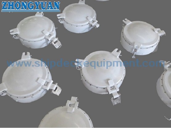
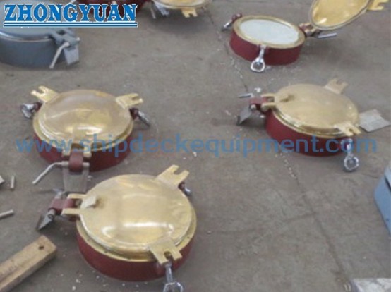
A3: Provide nominal diameter, clear opening, wall cut-out, D1-D5 dimensions, frame depth, mounting-bolt circle and hole size, bolt quantity, hinge and opening hand, glass and gasket details, material, finish, class requirement, and clear photos or an existing drawing.