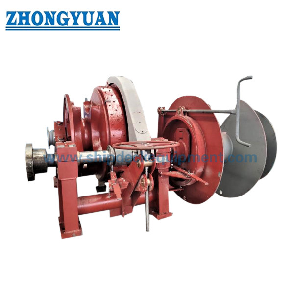
Φ64 mm Electro-Hydraulic Combined Anchor Windlass & Mooring Winch for Ship Deck
Product Overview
The Φ64 mm electro-hydraulic combined anchor windlass and mooring winch is a ship-deck machinery unit that combines powered anchor-chain handling with a separate mooring-drum function on one common drive arrangement. The cable lifter / gypsy engages the vessel’s 64 mm stud-link anchor chain for heaving and paying out the bower anchor, while the drum is used for the project-specified mooring rope operation. The anchoring and mooring functions share machinery space, but their load ratings, brake duties, rope or chain data, and class checks must be treated separately.
For a 64 mm chain, the anchor-windlass design basis depends on chain grade, maximum anchorage depth, certified chain breaking strength, chain-stopper arrangement, anchor particulars, and the selected classification society. The current IACS UR A3 reference formula gives approximately 174.1 kN continuous-duty pull for Grade 2 / AM2 and 194.6 kN for Grade 3 / AM3 when the maximum anchorage depth does not exceed 82.5 m. The final gypsy profile, brake capacity, hydraulic power unit, foundation, controls, and mooring-drum specification should therefore be confirmed against the vessel GA, chain certificate, and project approval requirements.
Quick Specifications
Main Technical Parameters
Main selection data for the Φ64 mm combined anchor windlass and mooring winch. Values identified as reference or to be confirmed should be finalized against the approved project data.
|
Parameter |
Value / Reference |
Selection Note |
|---|---|---|
| Anchor chain diameter | Φ64 mm | Match actual certified stud-link chain dimensions and gypsy pocket profile. |
| Chain grade | AM2 / AM3 | Confirm from chain certificate and classification requirement. |
| Continuous-duty pull ≤82.5 m | AM2: 174.1 kN | AM3: 194.6 kN | IACS UR A3 basis: Grade 2 = 42.5d² N; Grade 3 = 47.5d² N. |
| Temporary overload pull, minimum | AM2: 261.2 kN | AM3: 291.9 kN | At least 1.5 × continuous-duty pull for at least 2 minutes. |
| Mean anchor-chain hoisting speed | ≥9 m/min | Reference minimum under the applicable windlass test condition. |
| Reference brake holding load with independent chain stopper | AM2: ~982 kN | AM3: ~1405 kN | Reference 45% MBL basis; verify against the actual certified chain MBL and class-approved arrangement. |
| Electro-hydraulic motor power | 55 kW published reference | Not a universal Φ64 mm value; verify hydraulic pressure/flow, efficiency, duty, and AM2/AM3 design. |
| Mooring drum rated pull / speed / rope capacity | To be confirmed | Specify rope type, diameter, MBL, first-layer pull, capacity, and operational requirement. |
| Reference machinery arrangement | Single gypsy + single drum | Confirm side, shaft arrangement, brake/clutch layout, and deck orientation by GA drawing. |
Engineering Note: The 174.1 / 194.6 kN values are windlass continuous-duty pull references for one anchor at a time and an anchorage depth up to 82.5 m; they are not product SWL values. For anchorage depths above 82.5 m, an additional depth term applies. Brake holding, chain stopper, deck foundation, and mooring-drum ratings are separate design checks.
Selection & Inquiry Guide
Step 1: Confirm anchor-chain data → Φ64 mm chain, AM2 / AM3 grade, chain certificate, pitch / link dimensions, certified minimum breaking load, anchor mass, and maximum anchorage depth.
Step 2: Confirm anchoring performance → required continuous pull, short-term overload pull, recovery speed, number of anchors operated at one time, and whether an independent chain stopper is fitted.
Step 3: Confirm mooring-drum requirement → rope type, diameter, MBL, required first-layer pull, working speed, storage capacity, number of layers, and preferred drum / warping arrangement.
Step 4: Confirm deck arrangement → hawse-pipe lead, chain stopper position, chain locker lead, gypsy centerline, rope lead / fleet angle, machinery handedness, maintenance access, foundation, and local deck reinforcement.
Step 5: Confirm electro-hydraulic system → ship power supply, motor rating, hydraulic pressure and flow, HPU location, control station, manual proportional control requirement, protection / relief-valve arrangement, and emergency operation requirement.
Step 6: Confirm commercial and approval scope → classification society, drawing approval / survey requirement, FAT and onboard test scope, surface treatment, quantity, delivery destination, required delivery time, and vessel GA or reference drawing.
Structure
Electric motor & hydraulic power unit | Hydraulic motor | Reduction gearbox | Φ64 mm cable lifter / gypsy | Gypsy clutch | Anchor-chain brake | Mooring drum | Drum brake / clutch as specified | Main shaft & bearings | Base frame / foundation interface | Hydraulic valves & piping | Local / remote control station
Windlass, Hydraulic & Installation Engineering Advantages
Custom Attributes
How It Works
Ship electrical supply powers the hydraulic pump unit → pressurized oil drives the hydraulic motor → gearbox transmits torque to the main shaft → engaged gypsy clutch rotates the Φ64 mm cable lifter for heaving / paying out anchor chain → anchor brake and chain stopper control / secure the chain as arranged → mooring drum operates the specified rope independently through its clutch / brake arrangement → local or remote controls regulate direction and speed
Applications
Bulk carriers | General cargo ships | Tankers | Container vessels | Multi-purpose vessels | Merchant-ship bow anchoring stations | Newbuilding projects | Deck machinery replacement / retrofit projects
Certifications & Advantages
Windlass design approval, material certification, survey attendance, shop testing, onboard testing, and final certificate scope can be arranged according to the project specification and are subject to the selected classification society’s approval procedure. IACS Unified Requirements are minimum requirements; the vessel’s class rules may impose additional requirements.
Certification: CCS, NK, BV, ABS, DNV, LR, KR, IRS, RS, RINA, CRS, Makers Test Certificate.
Drawing & Photos
FAQ
Q1: Are 174.1 kN and 194.6 kN the SWL of the Φ64 mm windlass?
A1: No. They are reference continuous-duty anchor-chain pulls for 64 mm Grade 2 / AM2 and Grade 3 / AM3 chain under the IACS UR A3 basis for anchorage depth up to 82.5 m. They should not be described as a generic SWL or as the mooring-drum rating.
Q2: Why does the chain-stopper arrangement affect the brake / holding requirement?
A2: The windlass holding-load and brake design case is related to the certified chain minimum breaking strength. Under the IACS UR A3 basis, 45% of chain MBL may be used when an independent chain stopper is fitted; without a chain stopper, the brake must be checked at 80% of chain MBL. The actual arrangement and chain certificate must therefore be confirmed before final design.
Q3: What information is required for a reliable quotation and GA drawing?
A3: Provide the 64 mm chain grade and certificate data, anchor mass, maximum anchorage depth, hawse pipe and chain-stopper arrangement, mooring-rope diameter / MBL / capacity, required drum pull and speed, ship power supply, HPU arrangement, machinery orientation, deck foundation information, classification society, quantity, destination, and required delivery time.