Cast Steel Bar Type Anchor Chain Stopper for Small Vessels Anchoring| CB* 286-84
Product Overview
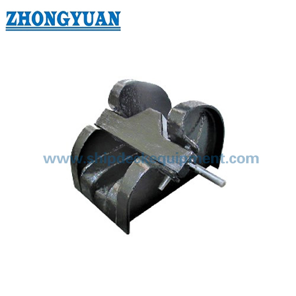
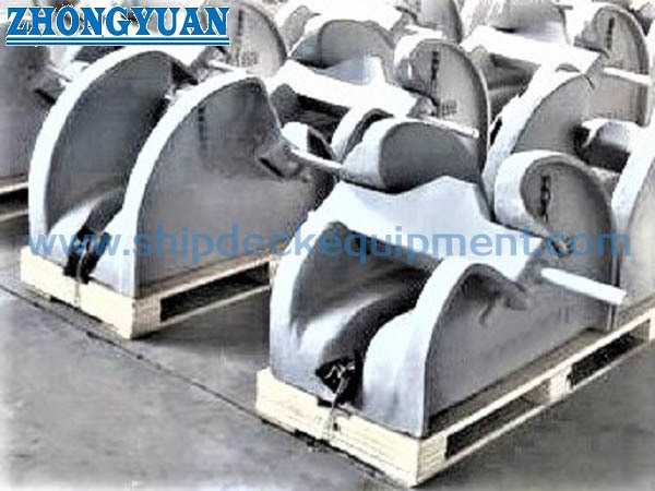
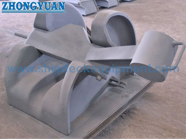
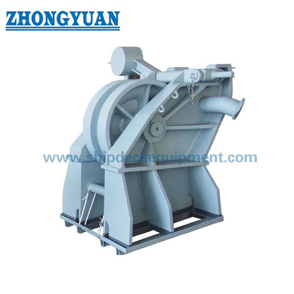
The CB* 286-84 cast steel bar type anchor chain stopper is a lever-operated securing device installed by welding on a forecastle deck foundation or other approved anchor-chain foundation. The cast steel body and operating bar are arranged in the anchor chain lead so the bar can engage the chain path and restrain chain movement when the vessel is underway or when the anchor chain needs to be mechanically secured.
This size series covers 12.5 to 68 mm anchor chain and is particularly suitable for small boats, inland waterway vessels, barges, small tugboats, workboats, and harbor craft using a compact anchoring arrangement. We can also coordinate the anchor windlass, chain guide roller, chain stopper, chain centerline, and foundation interfaces as one anchoring equipment package. CB* 286-84 is a legacy standard; for newbuilding projects, the required standard should be confirmed because CB/T 4462-2016 replaced CB* 286-1984.
Quick Specifications
Main Technical Parameters
| Anchor Chain Diameter(mm) |
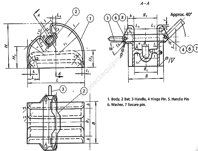
B | H | L | Welding Foot f |
Body Weight (kg) |
| 12.5-14 | 142 | 162 | 235 | 5 | 20 |
| 16-17.5 | 170 | 190 | 270 | 6 | 25 |
| 19-20.5 | 193 | 216 | 320 | 6 | 30 |
| 22-24 | 219 | 241 | 345 | 7 | 37 |
| 26-28 | 241 | 270 | 385 | 7 | 46 |
| 30-32 | 274 | 305 | 435 | 9 | 56 |
| 34-36 | 304 | 342 | 490 | 9 | 69 |
| 38-40 | 336 | 378 | 540 | 10 | 85 |
| 42-44 | 366 | 412 | 590 | 10 | 108 |
| 46-48 | 397 | 450 | 640 | 12 | 139 |
| 50-52 | 428 | 491 | 695 | 12 | 173 |
| 54-56 | 457 | 528 | 745 | 13 | 210 |
| 58-60 | 488 | 564 | 795 | 13 | 255 |
| 62-64 | 517 | 600 | 850 | 14 | 305 |
| 66-68 | 547 | 635 | 900 | 14 | 363 |
Selection & Inquiry Guide
Step 1: Confirm whether the order follows CB* 286-84 for replacement / legacy drawing compatibility or CB/T 4462-2016 for a new standard-based project.
Step 2: Confirm anchor chain diameter, chain grade, link pitch and width, and the anchor chain standard or maker's chain drawing. Nominal chain diameter alone may not fully define the engagement geometry.
Step 3: Provide the anchoring arrangement or GA drawing showing the hawse pipe / chain guide roller, stopper, windlass chain wheel, chain centerline height, lead direction, and available installation space.
Step 4: Confirm the cast steel body grade, material requirements for the operating bar, shaft and optional counterbalance, plus the required surface treatment and final vessel coating system.
Step 5: Confirm foundation plate, deck reinforcement, welding detail, WPS requirement, inspection scope, material traceability, and classification society requirement before production.
Step 6: Provide quantity, required delivery time, delivery destination, vessel type, newbuilding or replacement status, and reference photos or an existing stopper drawing when available.
Structure
Cast steel body | Lever-operated bar / blade | Pivot shaft | Anchor-chain seating and engagement area | Optional counterbalance | Deck-welded foundation interface | Project-specified coating
Anchoring Arrangement, Casting & Installation Advantages
Custom Attributes
How It Works
Anchor chain runs from the hawse / guide arrangement toward the windlass → Bar is raised for paying out or heaving the chain → Chain is positioned at the required securing point → Lever-operated bar is lowered to engage and restrain the chain path → Final securing and operating checks follow the vessel's approved procedure
Applications
Small boats | Inland waterway vessels | Barges | Small tugboats | Workboats | Harbor craft | Compact forecastle anchoring systems | Newbuilding, replacement, and retrofit projects
Certifications & Advantages
Certificates and inspection can be arranged according to project requirement, material traceability, approved drawing, and classification society procedure. Certificate scope must be confirmed before quotation and is subject to class approval.
Certification: CCS, NK, BV, ABS, DNV, LR, KR, IRS, RS, RINA, CRS, Makers Test Certificate.
Drawing & Photos


FAQ
Q1: Is CB* 286-84 still the standard to use for a new vessel?
A1: CB* 286-84 remains relevant for replacement, repair, and vessels whose approved drawing specifies the legacy design. CB/T 4462-2016 replaced CB* 286-1984, so a newbuilding project should confirm the required standard with the shipyard, designer, owner, and classification society.
Q2: What should be checked when the stopper is supplied together with a windlass and chain guide roller?
A2: Confirm the complete chain route, chain centerline height, lead direction, chain wheel compatibility, stopper position, operating clearance, foundation interfaces, deck reinforcement, and access for crew operation and maintenance.
Q3: Does the supplied dimension table define the stopper holding load or test load?
A3: No. The supplied table provides chain diameter, B, H, L, weld foot f, and body weight. Holding load, proof test, acceptance criteria, and certificate scope must be confirmed from the applicable standard, class requirement, and approved project documents.