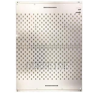
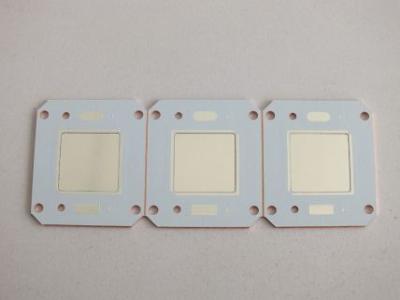
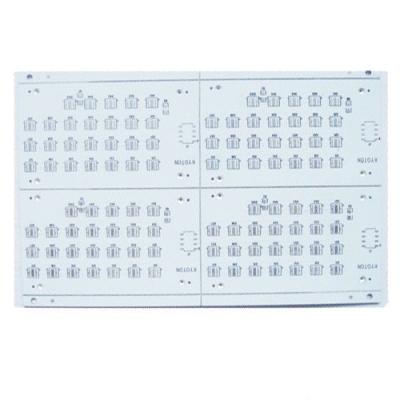
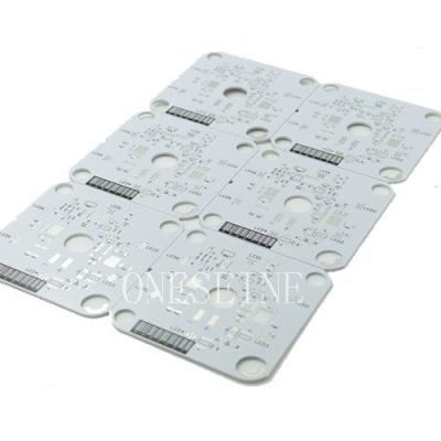
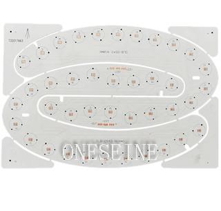
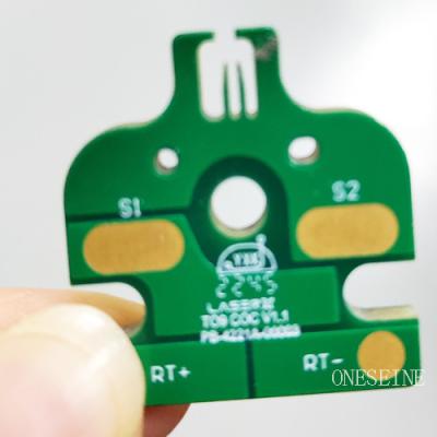
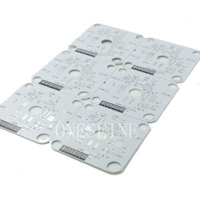
1 Layer Metal Core PCB Circuit Board Quick Turn One-Stop Service
PCB parameter:
Material:metal base
Brand:ONESEINE
Layer:1
Board size:120*80mm
Surface finish:HASL
Sample time:1-2days
Solder mask:Brown
Metal Core PCB Technology: Materials, Production & Design Guidelines
Core Material Variants
Metal core PCBs utilize specialized substrates categorized by thermal and mechanical properties. Aluminum cores (1-3 W/mK thermal conductivity) dominate 80% of applications due to cost efficiency (¥120-300/m²) and lightweight properties (2.7g/cm³), making them ideal for LED lighting and automotive power systems. Copper cores deliver superior thermal transfer (380-400 W/mK) for RF amplifiers and high-power converters, though at 3.2x the cost of aluminum with significant density penalties (8.96g/cm³). Iron alloy cores provide unique magnetic permeability (>10k μ) for motor controllers and EMC-sensitive environments, while composite aluminum-copper hybrids offer balanced thermal-mechanical performance (CTE 14 ppm/°C) in aerospace applications. For extreme environments, ceramic cores (AlN substrates at 170-230 W/mK) serve laser diodes and satellite systems, and flexible metal-polyimide constructions enable bend radii >5mm for curved displays and medical wearables.
Precision Manufacturing Process
Production involves 18 critical stages beginning with CNC-milled metal cores (5052/6061 Al or C1100 Cu) achieving ≤0.1mm/m² flatness tolerance. Surface preparation includes alkaline washing followed by anodization (aluminum) or antioxidant coating (copper). The dielectric lamination phase employs thermally conductive polymers like Bergquist HT-04503 (100μm±5μm) with <0.3°C-in²/W thermal resistance and >3kV AC breakdown voltage. Circuit fabrication supports copper weights from 1oz (35μm) to 10oz (350μm), with laser direct imaging enabling 0.15mm trace/space tolerances. Thermal management features include conductive epoxy via fills (0.8-1.5 W/mK) and 360° edge plating for chassis grounding. Each board undergoes rigorous validation including 500 thermal cycles (-55°C↔+150°C) and 3kV dielectric withstand testing.
Thickness Optimization Principles
Total PCB thickness combines metal core, dielectric, copper, and surface finishes. Standard configurations use 1.0mm aluminum cores (±0.05mm) or 1.2mm copper bases, where increasing core thickness by 1mm reduces thermal resistance (θja) by 15%. Dielectric layers typically measure 75-100μm (±5μm), with thinner layers enhancing heat transfer. Copper weights range from 35μm (1oz) for signal layers to 350μm (10oz) for power planes, directly impacting current capacity. Surface finishes like ENIG (3-5μm Ni + 0.05-0.1μm Au) affect solderability. Overall thickness ranges from 0.8mm for compact LED arrays to 6.5mm for high-power converters, with automotive LED boards typically at 1.6mm (1.0mm Al + 100μm dielectric) and server PSUs at 3.0mm with 2.0mm copper cores.
Performance & Certification
Thermal benchmarks show 1.0mm aluminum cores achieve 1.8°C/W resistance, while copper cores reach 0.6°C/W at 100W dissipation. Ceramic (AlN) cores deliver peak performance at 0.4°C/W. All production complies with IATF 16949 (automotive), ISO 13485 (medical), and UL 94 V-0 flammability standards. Prototype lead times start at 7 days for 5-panel batches, with volume production (minimum 1m²) shipping in 15 days. Quality assurance includes ASTM D5470 thermal resistance testing and SEMI-THERM validated performance data.