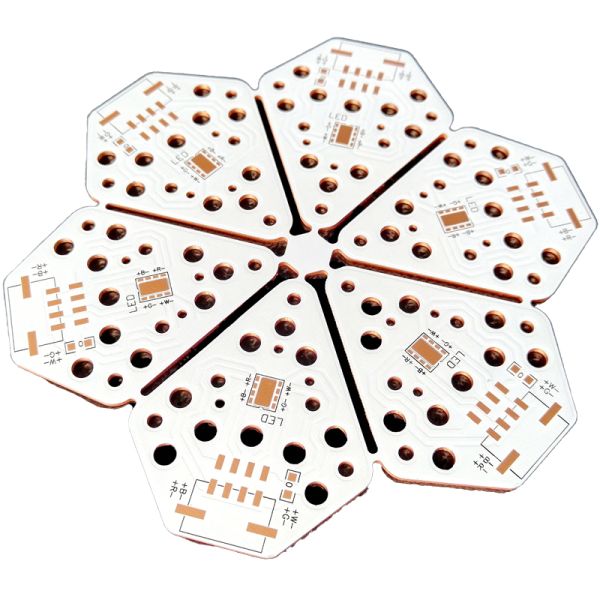
As luminaires, displays, and electronic products get thinner, a 1.5–2.0 mm board is often simply too thick. The 1.0 mm single-layer aluminum PCB solves this: copper layer, dielectric, and aluminum core together total just one millimeter, yet the board still spreads heat orders of magnitude better than an FR4 board of the same thickness — where the epoxy core traps heat and forces you to add pads, screws, and external heat sinks.
A typical stackup is 35 µm copper + 75–100 µm dielectric + 0.85–0.9 mm aluminum alloy (5052/6061), with thermal conductivity of 1.0–2.0 W/m·K in the standard grade, or up to 3.0 W/m·K with the high-conductivity dielectric for compact high-power designs. Thinner aluminum also shears, routes, and punches cleanly, enabling low-cost, tight-tolerance outlines and lightening holes.
Despite the slim profile, the board remains flat and rigid enough for reflow and automated SMT assembly, and can be supplied panelized with rails. It is produced under our ISO 9001 / ISO 13485 / IATF 16949 quality systems and is RoHS compliant and UL certified.
| Layer count | 1 layer (single-sided copper on aluminum base) |
|---|---|
| Total board thickness | 1.0 mm standard; 0.5 / 0.8 / 1.2 / 1.6 mm customizable |
| Typical 1.0 mm stackup | 35 µm Cu + 75–100 µm dielectric + 0.85–0.9 mm aluminum (5052/6061) |
| Thermal conductivity | 1.0 – 2.0 W/m·K standard; up to 3.0 W/m·K optional |
| Copper thickness | 1 – 3 oz (35 – 105 µm) |
| Dielectric breakdown voltage | ≥ 2 kV AC (≥ 3 kV with high-conductivity grade) |
| Min trace width / spacing | 0.15 mm / 0.15 mm |
| Max panel size | 600 × 500 mm (thin boards ship panelized for stiffness) |
| Surface finish | OSP, HASL (LF), ENIG, Immersion Silver/Tin |
| Solder mask | White (default), Green, Black, Blue, Matt Black |
| Board outline | CNC routing, punching, V-scoring, laser profiling; lightening holes available |
| Bending | Slight bending/curved forming available on request (radius per DFM) |
| Testing | 100% electrical test (flying probe / E-test) |
| Prototype lead time | 5 – 7 working days; mass production 10 – 15 working days |
A: For most lighting and module applications, yes. The 5052/6061 aluminum core gives a 1.0 mm MCPCB bending stiffness comparable to or better than 1.6 mm FR4. For larger boards or heavy screw-mounted components, we can recommend stiffening ribs, mounting points, or a 1.2–1.6 mm core.
A: Thermal conductivity through the dielectric is unaffected by core thickness; a thin board mainly has less lateral spreading area. It comfortably handles typical LED-module densities (e.g., 0.2–0.5 W/cm² with standard dielectric). For denser power, pair 1.0 mm with the 2.0–3.0 W/m·K dielectric, or mount the board on a chassis that acts as an extended heat sink.
A: Yes. Total thickness is customizable from about 0.5 mm to 3.0 mm; we will build the copper / dielectric / aluminum split that meets your thermal and mechanical targets.
A: Thin aluminum allows slight single-bend forming (e.g., for curved lamps) within angle and radius limits confirmed by DFM review. For true dynamic flexing, a flexible PCB is the right product instead.
A: Thin boards are panelized with rails or supplied in small sub-panels, vacuum-sealed with ESD protection, and packed rigidly in export cartons with edge protection.
A: Yes — one-stop PCBA including SMT and through-hole assembly works the same as for standard MCPCBs; the flat, warp-resistant core actually improves SMT yield.
A: Prototype quantities of 1–10 pcs are welcome. Volume pricing typically becomes attractive from around 500 pcs or 1 m².
A: Send Gerber files plus your thickness, copper, and thermal requirements. Quotation and DFM feedback within 24 hours; prototypes in 5–7 working days.