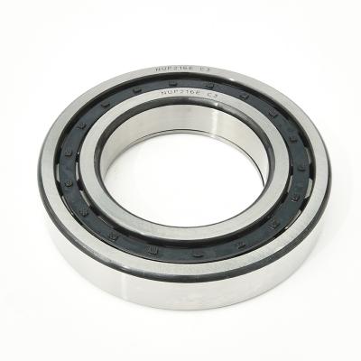
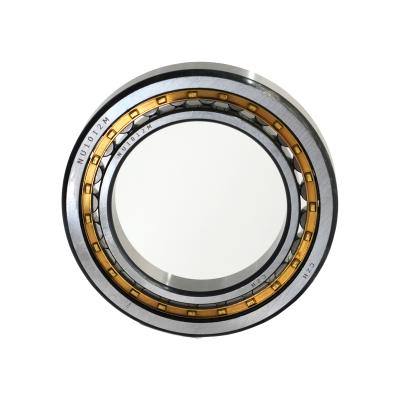
Cylindrical roller bearing
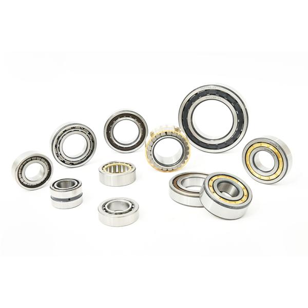
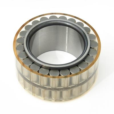
Cylindrical roller bearings is using cylindrical rollers as its roller element, Its outer ring has big wall thickness which allow it to work in heavy load conditions. Besides the high radial load capacity,this kind of bearings are allowed to carry partial axial loading.
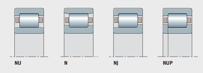
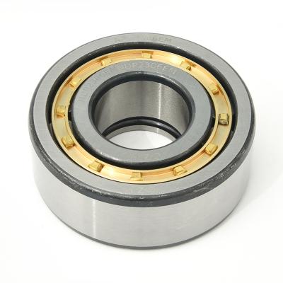
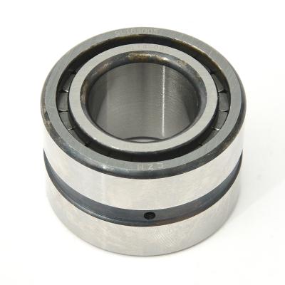
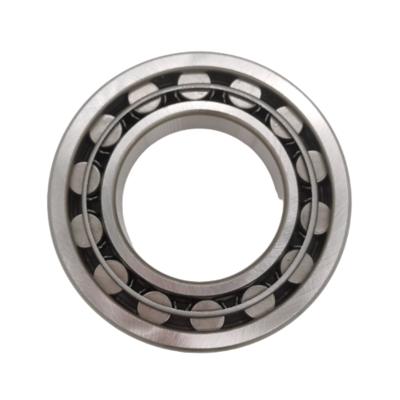
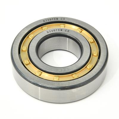
According to different rib locations,Part numbers of caged type cylindrical roller bearings mainly contain: NU,NJ,NUP,N,etc.See below photo1. The cage can be made of different materials:Nylon,steel and brass.Part number with suffix “ECP(ETVP)”means nylon cage,“M” means brass cage,if without any suffix,it means steel cage.See Table 1. Part number“E”means enhanced cage design.
(Photo 1)
Bearing series and cage material (Table1)
Series | Nylon 66 holder ETVP | Solid brass holder M |
NU10 | - | follow 05 |
NU19 | - | follow 92 |
NU2..-E | to 26 | follow 28 |
NU3..-E | to 28 | follow 30 |
NU4 | - | all |
NU22..-E | to 26 | follow 28 |
NU23..-E | to 22 | follow 24 |
N2..-E | to 20,22~26 | 21,follow 28 |
N3..-E | to 16 | follow 17 |
NJ2..-E | to 26 | follow 28 |
NJ3..-E | to 28 | follow 30 |
NJ4 | - | all |
NJ22..-E | to 26 | follow 28 |
NJ23..-E | to 22 | follow 24 |
NUP2..-E | to 26 | follow 28 |
NUP3..-E | to 28 | follow 30 |
NUP22..-E | to 26 | follow 28 |
NUP23..-E | to 22 | follow 24 |
1,Accuracy of cylindrical roller bearings
Radial cylindrical roller bearings are available in various tolerance classes and clearance groups.For tolerances of bearings,they are chosen by engineering section.The internal clearances are normally produced with C0 class, however,Class C2,C3 and C4 maybe obtained on request.
Bearing internal radial clearance according to DIN620-4 standard(Table2)
Inside Diameter d mm | Internal radial clearance | ||||||
CN μm | C3 μm | C4 μm | |||||
greater than | arrive | min. | max. | min. | max. | min. | max. |
- | 24 | 20 | 45 | 35 | 60 | 50 | 75 |
24 | 30 | 20 | 45 | 35 | 60 | 50 | 75 |
30 | 40 | 25 | 50 | 45 | 70 | 60 | 85 |
40 | 50 | 30 | 60 | 50 | 80 | 70 | 100 |
50 | 65 | 40 | 70 | 60 | 90 | 80 | 110 |
65 | 80 | 40 | 75 | 65 | 100 | 90 | 125 |
80 | 100 | 50 | 85 | 75 | 110 | 105 | 140 |
100 | 120 | 50 | 90 | 85 | 125 | 125 | 165 |
120 | 140 | 60 | 105 | 100 | 145 | 145 | 190 |
140 | 160 | 70 | 120 | 115 | 165 | 165 | 215 |
160 | 180 | 75 | 125 | 120 | 170 | 170 | 220 |
180 | 200 | 90 | 145 | 140 | 195 | 195 | 250 |
200 | 225 | 105 | 165 | 160 | 220 | 220 | 280 |
225 | 250 | 110 | 175 | 170 | 235 | 235 | 300 |
250 | 280 | 125 | 195 | 190 | 260 | 260 | 330 |
280 | 315 | 130 | 205 | 200 | 275 | 275 | 350 |
315 | 355 | 145 | 225 | 225 | 305 | 305 | 385 |
355 | 400 | 190 | 280 | 280 | 370 | 370 | 460 |
400 | 450 | 210 | 310 | 310 | 410 | 410 | 510 |
450 | 500 | 220 | 330 | 330 | 440 | 440 | 550 |
500 | 560 | 240 | 360 | 360 | 480 | 480 | 600 |
560 | 630 | 260 | 380 | 380 | 500 | 500 | 620 |
630 | 710 | 285 | 425 | 425 | 565 | 565 | 705 |
2,Mounting of cylindrical roller bearing
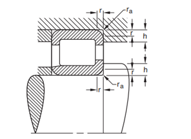
The bearing inner and outer rings should be mounted against the stepped portion on the shaft and the shoulder of the housing.Under no circumstances should they interfere with the shaft or housing fillets.For this reason,the maximum fillet radius ras max of the mating component must be no greater than the minimum chamfer dimension of the corresponding cylindrical roller bearing ring corner rs min
The shoulder of the mating components must be such that, even with the maximum permissible single chamfer dimension of corresponding bearing ring,there is an adequate contact surface area.Table 3 lists the maximum fillet radius ras max and the minimum shoulder height.At high axial loads the ribs must be supported over half their height.
rs min
| ras max
| h min Bearing series | |
10 series | 2..E 3..E 22..E 23..E | ||
mm in. | mm in. | mm in. | mm in. |
0.3 0.0118 | 0.3 0.0118 | 1 0.0394 | 1.2 0.0472 |
0.6 0.0236 | 0.6 0.0236 | 1.6 0.630 | 2.1 0.0827 |
1 0.0394 | 1 0.0394 | 2.3 0.0905 | 2.8 0.1102 |
1.1 0.0433 | 1 0.0394 | 3 0.1181 | 3.5 0.1378 |
1.5 0.0591 | 1.5 0.0591 | 3.5 0.1378 | 4.5 0.1772 |
2 0.0787 | 2 0.0787 | 4.4 0.1732 | 5.5 0.2165 |
2.1 0.0827 | 2.1 0.0827 | 5.1 0.2008 | 6 0.2362 |
3 0.1181 | 2.5 0.0984 | 6.2 0.2441 | 7 0.2756 |
4 0.1575 | 3 0.1181 | 7.3 0.2874 | 8.5 0.3346 |
5 0.1969 | 4 0.1575 | 9 0.3543 | 10 0.3937 |
6 0.2362 | 5 0.1969 | 11.5 0.4528 | 13 0.5118 |