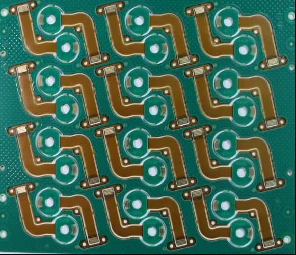
4-layer board Black oil HDI PCB
4-layer board Black oil HDI PCB is a PCB that achieves higher circuit density by using thinner lines, smaller apertures and denser wiring design. This PCB technology can achieve more circuit connections in a limited space by adopting more advanced manufacturing processes and design technologies, and is widely used in mobile phones, tablets, computers, equipment, automobiles, electronics and other medical fields.
Product Features:
-
Microvias (Micro-Through-Holes): These are very small vias (typically $leq 150 mu m$ in diameter) used to connect different layers. They are usually laser-drilled.
-
Blind and Buried Vias: HDI boards utilize vias that do not pass through the entire board (blind vias) or connect only internal layers (buried vias), freeing up surface space for component placement and routing.
-
Finer Lines and Spaces: The trace width and spacing are much smaller than traditional PCBs (often $< 100 mu m$).
-
High Component Density: The use of microvias and finer traces allows for more components to be placed closer together on the board.
-
Via-in-Pad Technology: This involves placing a microvia directly in the copper pad of a component, which further conserves routing space and improves signal performance.
Core Manufacturing Challenges
-
Ultra-fine Line and Space Fabrication :HDI boards require line widths and spaces (L/S) as small as 25μm/25μm or even finer. Controlling undercutting, line discontinuity, and copper uniformity during etching is extremely difficult, as minor process variations can lead to open or short circuits.
-
High-Precision Drilling for Microvias: Microvias (typically ≤150μm in diameter) demand advanced laser drilling or mechanical micro-drilling techniques. Issues like drill breakage, uneven hole walls, and thermal damage to the substrate (especially for laser drilling) are major hurdles, directly affecting interconnection quality.
-
Layer-to-Layer Alignment Accuracy : Multiple stacked layers (often ≥8 layers) require precise alignment, with registration tolerances as tight as ±10μm. Any misalignment between layers can cause microvia misconnection, reducing yield and board reliability.
-
Reliability Control of Stacked/Buried Vias: Stacked or buried microvias need consistent plating thickness (usually ≥20μm) to ensure conductivity and mechanical strength. Voids, poor adhesion, or uneven plating within vias can lead to premature failure under thermal cycling or vibration.
-
Surface Finish and Solderability: Fine-pitch components (e.g., 01005 chips or CSPs) on HDI boards require uniform surface finishes (e.g., ENIG, Immersion Silver). Controlling finish thickness, avoiding oxidation, and ensuring solder joint reliability are critical, as small defects can cause soldering failures.