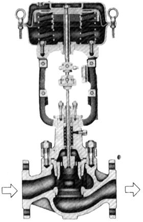
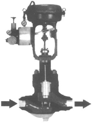
HCB cage-type double-seat control valve
The HCB cage-type double-seat control valve is a pressure-balanced control valve. The fluid channel of the valve body is S-streamlined, and it is also equipped with a guide vane that improves the smooth flow of fluid around the sleeve. It has the advantages of small pressure drop loss, large flow rate, wide adjustable range, high precision of flow characteristic curve, good dynamic stability, low noise, and little cavitation corrosion.
The control valve is equipped with a multi-spring diaphragm actuator, which has a compact structure and large output force. It is suitable for controlling high-pressure difference fluids at high or low temperatures.
Cv value and stroke are shown in Table 1 Table 1 |
Nominal diameter(mm) | 40 | 50 | 65 | 80 | 100 | 150 | 200 |
Valve seat diameter(mm) | 25 | 32 | 40 | 32 | 40 | 50 | 40 | 50 | 65 | 50 | 65 | 80 | 65 | 80 | 100 | 100 | 125 | 150 | 125 | 150 | 200 |
Rated Cv value | High-capacity sleeve | Equal percentage | | | 36 | | | 60 | | | 100 | | | 140 | | | 220 | | | 420 | | | 820 |
Linear | | | 40 | | | 75 | | | 110 | | | 150 | | | 240 | | | 435 | | | 850 |
High-precision sleeve | 11 | 17 | 24 | 17 | 24 | 44 | 24 | 44 | 68 | 44 | 68 | 99 | 68 | 99 | 175 | 175 | 275 | 360 | 275 | 360 | 650 |
Rated stroke(mm) | 25 | 38 | 50 | 75 |
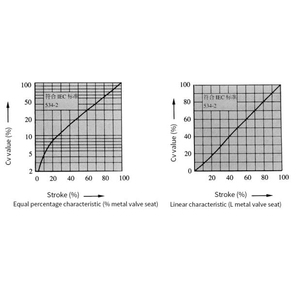
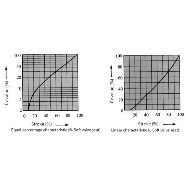
High-precision flow characteristic curve


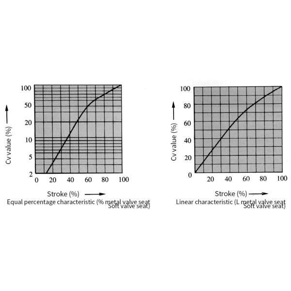
Flow Characteristic Curve of High-Capacity Sleeve

Allowable pressure difference
Ⅰ. Metal valve seat (see Tables 2 and 3) A. Air-to-close valve Tables 2 |
Actuator | Supply pressure (MPa) | Spring range (MPa) | Positioner | Allowable pressure difference(MPa) |
Nominal diameter(mm) |
40 | 50 | 65 | 80 | 100 | 150 | 200 |
HA2D | 0.14 | 0.02-0.10 | with or With out | 0.99 | 0.77 | 0.66 | 0.54 | 0.42 | - | - |
0.16 | 0.02-0.10 | with | 4 4.92 | 3.8 | 3.29 | 2.74 | 2.08 | - | - |
0.40 | 0.08-0.24 | with | 4 10 | 4 10 | 4 9.87 | 4 8.23 | 4 6.28 | - | - |
HA3D | 0.14 | 0.02-0.10 | with or With out | 1.75 | 1.37 | 1.17 | 0.97 | 0.74 | 0.52 | - |
0.16 | 0.02-0.10 | with | 4 8.7 | 4 6.7 | 4 5.8 | 4 4.87 | 3.7 | 2.61 | - |
0.40 | 0.08-0.24 | with | 4 10 | 4 10 | 4 10 | 4 10 | 4 10 | 4 7.86 | - |
HA4D | 0.14 | 0.02-0.10 | with or With out | - | - | 2.02 | 1.67 | 1.28 | 0.90 | 0.74 |
0.16 | 0.02-0.10 | with | - | - | 4 10 | 4 8.39 | 4 6.36 | 4 4.5 | 3.7 |
0.40 | 0.08-0.24 | with | - | - | 4 10 | 4 10 | 4 10 | 4 10 | 4 10 |
B. Air-to-open valve Table 3 |
Actuator | Supply pressure (MPa) | Spring range(MPa) | Positioner | Allowable pressure difference(MPa) |
Nominal diameter(mm) |
40 | 50 | 65 | 80 | 100 | 150 | 200 |
HA2R | 0.14 | 0.02-0.10 | with or With out | 0.99 | 0.77 | 0.66 | 0.54 | 0.42 | - | |
0.28 | 0.08-0.24 | with | 4 6.81 | 4 5.39 | 4 4.6 | 3.84 | 2.93 | - | - |
HA3R | 0.14 | 0.02-0.10 | with or With out | 1.75 | 1.37 | 1.17 | 0.97 | 0.74 | 0.52 | - |
0.28 | 0.08-0.24 | with | 4 10 | 4 9.57 | 4 8.17 | 4 6.8 | 4 5.18 | 3.67 | - |
HA4R | 0.14 | 0.02-0.10 | with or With out | - | - | 2.02 | 1.67 | 1.28 | 0.90 | 0.74 |
0.28 | 0.08-0.24 | with | - | - | 4 10 | 4 10 | 4 8.97 | 4 6.3 | 4 5.1 |
VA5R | 0.14 | 0.02-0.10 | with or With out | | | | | 1.75 | 1.23 | 1.02 |
0.14 | 0.04-0.12 | with or With out | - | | - | - | 4 5.2 | 3.7 | 3.07 |
0.28 | 0.08-0.24 | with | | | | | 4 10 | 48 | 47 |
VA6R | 0.40 | 0.19-0.35 | with | - | | - | - | 4 10 | - | - |
0.50 | 0.19-0.40 | with | | - | | - | - | 4 10 | - |
Remarks: 1.The numbers in the dark boxes indicate the standard specification actuators matched with the valve. 2.The maximum allowable pressure difference shall not exceed the maximum value specified in ANSI B16.34 or JIS B2201 standards. 3.In the same cell, the number above is the allowable pressure difference when the valve is fully open, and the number below is the allowable pressure difference when the valve is closed. |