Inner Valve Components
Valve core type | Upper - guided single - seat cylindrical plug valve core |
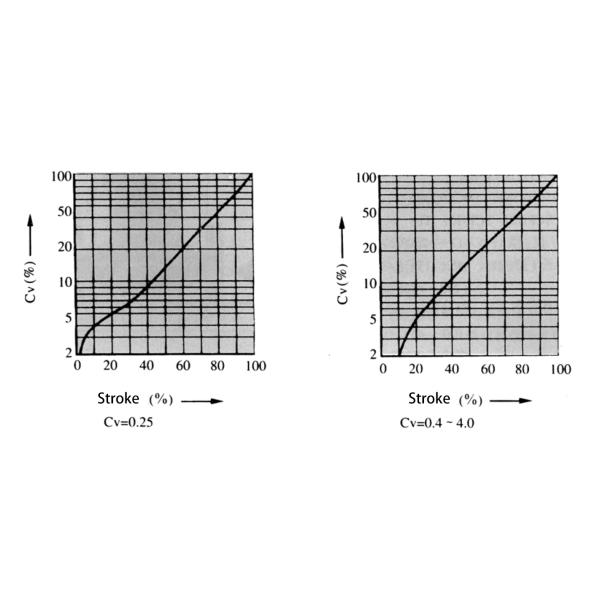
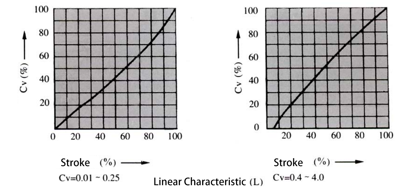
Flow Characteristics | High - precision flow characteristic, refer to Figure 2; High - capacity flow characteristic, refer to Figure 1; Quick - opening characteristic: Quick - opening valve core |
Working range | Working temperature and pressure difference of soft valve seat, refer to Figure 3; Working temperature and pressure difference of Stellite surfacing, refer to Figure 4 |
Materials | 1Cr18Ni9Ti, 0Cr17Ni12Mo2, Stellite surfacing |
Actuator
Type | HA multi - spring thin - film actuator |
Diaphragm material | Ethylene - propylene rubber nylon |
Spring range | 0.02 - 0.10, 0.08 - 0.24MPa |
Supply pressure | 0.14, 0.16, 0.28MPa |
Air source connector | Rc 1/4 |
Ambient temperature | - 30 - + 70℃ (Note: This valve can also be equipped with VA5, VA6 and VP actuators) |
Valve action type | Air - to - open type, Air - to - close type |
Accessories | Positioner, Handwheel mechanism, Pneumatic valve position transmitter, etc. |
Performance
Leakage rate | Metal valve seat: In line with standard ANSI B16.104 IV level, less than 0.01% of the rated Cv; Polytetrafluoroethylene valve seat: In line with standard ANSI B16.104 VI level, less than 10 - 7 of the rated Cv; Stellite surfacing welded valve seat, less than 10 - 7 of the rated Cv (quick - opening valve core) |
Hysteresis | 1% (with positioner), 3% (without positioner) |
Linearity | ± 1% (with positioner), ± 5% (without positioner) (Note: Using standard V - type polytetrafluoroethylene packing) |
Adjustable range | 50:1 |
Cv Value and Stroke (See Table 1)
Nominal diameter (mm) | 40 | 50 | 65 | 80 | 100 | 150 | 200 | |||||||||||||||
Valve seat diameter (mm) | 25 | 32 | 40 | 32 | 40 | 50 | 40 | 50 | 65 | 50 | 65 | 80 | 65 | 80 | 100 | 100 | 125 | 150 | 125 | 150 | 200 | |
Rated Cv value | High - precision valve core | 10 | 17 | 24 | 17 | 24 | 44 | 24 | 44 | 68 | 44 | 68 | 99 | 68 | 99 | 175 | 175 | 275 | 360 | 275 | 360 | 640 |
High - capacity valve core | 30 | 50 | 85 | 125 | 200 | 420 | 700 | |||||||||||||||
Quick - opening valve core | 35 | 55 | 95 | 135 | 220 | 460 | 720 | |||||||||||||||
Rated stroke (mm) | Other valve cores | 25 | 38 | 50 | 75 | |||||||||||||||||
Rated stroke (mm) | Quick - opening valve core | 10 | 13 | 19 | 25 | 30 | 50 |
Figure 2 Flow Characteristic Curve | ||||||||||||||||||||
Actuator | Supply pressure (MPa) | Spring range (MPa) | Positioner | Allowable pressure difference(MPa) | ||||||||||||||||
Cv value | ||||||||||||||||||||
≤0.25 | 0.40 | 0.63 | 1.0 | 1.6 | 2.5 | 4.0 | ||||||||||||||
HA2D (HA2R) | 0.14 | 0.02~0.10 | On or off | 4.0 10 | 4.0 6.2 | 4.0 6.2 | 3.26 | 3.26 | 2.0 | 2.0 | ||||||||||
0.16 (0.28) | 0.02~0.10 (0.08~0.24) | On | - | 4.0 10 | 4.0 10 | 4.0 10 | 4.0 10 | 4.0 10 | 4.0 10 | |||||||||||
Note: 1. The maximum allowable pressure difference shall not exceed the maximum value specified in the ANSI B16.34 or JIS B2201 standards. |
Flange distance refers to Table 3. Unit of Table 3:mm | ||||||||||||||||||||
Nominal diameter | A | |||||||||||||||||||
ANSI 125 FF ANSI 150 RF JIS 10K FF RF PN 1.6 MPa | JIS 16K RF | ANSI 300 JIS 20,30K RF | ANSI 600 JIS 40K RF PN6.4 MPa | ANSI 150 RJ | ANSI 300 RJ | ANSI 600 RJ | JIS 20K LG | JIS 30K LG | ANSI 300 LG | ANSI 600 SW,BW | ||||||||||
20 | 184 | 190 | 194 | 206 | 206 | 206 | 198 | 208 | 203 | 206 | ||||||||||
25 | 184 | 193 | 197 | 210 | 197 | 210 | 210 | 198 | 212 | 206 | 210 |
Actuator | H | φB | C | E | ||||||
P | E1 | E2 | ||||||||
E21 | E2W | |||||||||
HA2D,R | 450 | 600 | 760 | 975 | 267 | 281 | 40 |
Connection form | Nominal pressure | P | E1 | E2 | ||||||
E21 | E2W | |||||||||
Flanged type | ANSI 125150 JIS 10K | 23 | 25 | 28 | 33 | |||||
ANAI 300600 JIS 16203040 | 24 | 26 | 29 | 34 | ||||||
welding SW | 21 | 23 | 26 | 31 |
Ordering Information
|