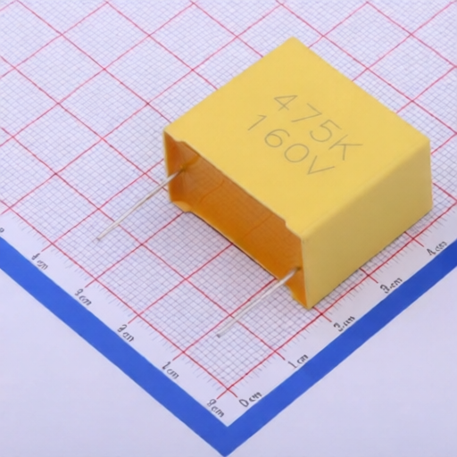
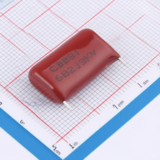
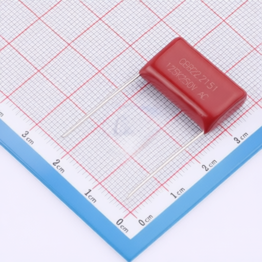
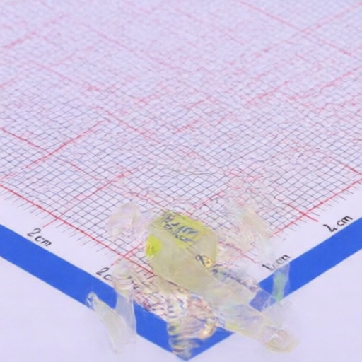
The CBB21/MPP series metallized polypropylene film capacitors are designed for electronic equipment applications. These capacitors feature an epoxy-encapsulated, non-inductive wound structure with tin-plated copper wire or tin-plated copper-clad steel wire leads. They offer excellent self-healing properties, low loss, and low internal temperature rise, encased in a flame-retardant epoxy resin powder coating. Ideal for DC blocking, coupling, decoupling, filtering, bypassing, and other high-frequency, DC, AC, and pulse circuits.
Model: CBB21/MPP
Specific Model Example: MPP684J2TD080B200ZR
General Electrical Characteristics:
| Item | Specification | Test Method |
|---|---|---|
| Climate Category | 40/105/21 | |
| Operating Temperature Range | -40 to +105 | (+85 to +105: Rated voltage derating coefficient 1.25%/) |
| Rated Temperature | 85 | |
| Capacitance Range | 0.001F to 6.8F | |
| Capacitance Tolerance | 5%(K), 10%(M) | |
| Rated Voltage (VDC) | 100V, 160V, 250V, 400V, 630V, 1000V, 1250V, 1600V, 2000V | |
| Dissipation Factor (DF) (1kHz, 20) | 0.0010 | |
| Insulation Resistance | 30,000M for C0.33F (100VDC, 60 sec) | |
| Insulation Resistance | 10,000M*F for C>0.33F (100VDC, 60 sec) | |
| Withstand Voltage | 1.6 UR(VDC), 5 seconds | |
| Terminal Strength (Tensile) | No visible mechanical damage | Wire diameter: 0.6 & 0.8mm; Load: 10N, Time: 10 seconds |
| Terminal Strength (Bending) | No visible mechanical damage | Wire diameter: 0.6 & 0.8mm; Force: 5N, 90 2 times |
| Solderability | 95% tinning rate on leads | Flux temp: 2455; Immersion time: 2.50.5 seconds |
| Solder Heat Resistance | No visible damage | Solder temp: 2605; Immersion time: 101 sec; Recovery time: 1-2 hours |
| Capacitance Change (Solder Heat Resistance) | C/C 3% | DF increase 0.004 (C1.0F, 10kHz); 0.004 (C>1.0F, 1kHz) |
| Temperature Cycling (Rapid Change) | No visible damage | A=-40, B=+105, 5 cycles; Duration: t=30min |
| Vibration | No visible damage | Amplitude 0.75mm or acceleration 98m/s (whichever is less); Frequency 10-500Hz; 3 directions, 2h each; Total 6h |
| Shock | No visible damage | 4000 times, acceleration 390m/s, pulse duration: 6ms |
| Capacitance Change (After Shock/Vibration) | C/C 5% | DF increase 0.004; Insulation Resistance IR/IR 50% |
| Damp Heat (Steady State) | No visible damage | Relative humidity 90-95%RH; Temp: 402; Duration: 21 days; Recovery time: 1-2 hours |
| Capacitance Change (Damp Heat) | C/C 5% | DF increase 0.002 (C1.0F, 10kHz); 0.004 (C>1.0F, 1kHz); Insulation Resistance IR/IR 50% |
| Endurance | No visible damage | T=85, 1000 hours; Applied voltage: 1.25UR |
| Capacitance Change (Endurance) | C/C 8% | DF increase 0.004; Insulation Resistance IR/IR 50% |
| Capacitance vs. Temperature | See details in source document | Static method, capacitor held at various temperatures (-40, +105, 20) |
| Charge/Discharge | No visible damage | 10,000 cycles; Charge voltage: UR; Charge time: 0.5s; Discharge time: 0.5s |
| Capacitance Change (Charge/Discharge) | C/C 5% | DF increase 0.005 (10KHz, CR1.0uF); 0.005 (1KHz, CR>1.0uF); Insulation Resistance IR/IR 50% |
Dimensions (Example: MPP684J2TD080B200ZR):
| P/N | Cap (F) | Tol. % | R.V VDC | DF (1KHz) % | Dimensions (mm) L (2.0) | W (1) | H (1) | T (1) | P 1.0 | d 0.05 |
|---|---|---|---|---|---|---|---|---|---|---|
| MPP684J2TD080B200ZR | 0.68 | 5 | 520 | 0.1 | 16.3 | 14.3 | 8.0 | 15.0 | 20 | 0.8 |
Product Code Explanation (Example):
| Position | Description | Example Code |
|---|---|---|
| 1-3 | Capacitor Model Code | MPP (for CBB21/MPP) |
| 4-6 | Nominal Capacitance Code | 684 (6.8 x 10^4 pF = 0.68F) |
| 7 | Capacitance Tolerance Code | J (5%) |
| 8-9 | DC Rated Voltage Code | 2T (520Vdc) |
| 10 | Lead Pitch Code | B (7.5mm) |
| 11-12 | Body Thickness Code | 08 (8.0mm) |
| 13 | Internal Feature Code | 0 |
| 14 | Lead Type Code | B (Straight Lead) |
| 15-16 | Lead Length & Taping Code | 20 (20mm) |
| 17-18 | Internal Feature Code | 00 |
| 19 | Environmental Requirement Code | R (RoHS & REACH Compliant) |
Packaging Information:
Storage Conditions:
Usage Rules:
Maximum Effective Voltage vs. Frequency Curve: (Refer to source document for graph)
Note: Typical values are tested under sinusoidal voltage, ambient temperature 85, and internal capacitor temperature rise T=10.
Product Electrical Characteristic Graphs: (Refer to source document for graphs)