GCE 1500V ESS High voltage lithium battery management system BMS quality long life solar energy storage system
Product system overview

Description
A battery management system (BMS) is an electronic system that monitors and controls the charging and discharging of a battery. It is typically used in applications where multiple batteries are connected in series or parallel, such as electric vehicles, renewable energy systems, and backup power systems.
Application scenarios
◎ PV power plant storage
◎ Island off-grid energy storage
◎ optical storage charge integration applications
◎ UPS power supply
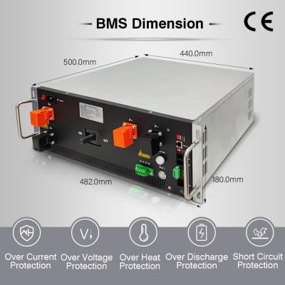
| | Rated current | 200A |
| operation voltage | 300V-1500V |
| Power consumption | ≤15W |
| Current sampling accuracy | 1%FSR |
| Insulation withstand voltage | 4000VDC <1mA 1min |
| Protection level | IP20 |
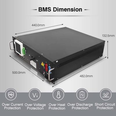
| Size(W*H*D) | 482*180*500(mm) |
| New Weight | ~22Kg |
| Communication
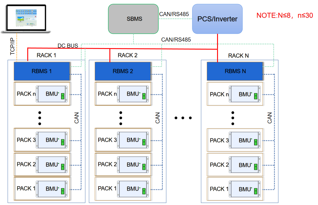
Interface | Communication port with BMU | CAN |
| Communication port with UPS | RS485/CAN |
| Communication port with SBMS | RS485/CAN |
| Communication with monitoring software | Ethernet |
| Basic Function | Battery charge & discharge management | Available |
| Battery temperature management | Available |
| IAP Upgrade | Available |
| System protection parameter setting | Available |
| Short circuit protection | available(1500V 20KA 20ms) |
| Pre-charge function | Available |
| Parallel circulation control | Available |
| Event record | Available(5000) |
| Dual power supply | Available(Battery + municipal power
supply, municipal power in priority) |
| Optional function | Insulation detection | Suitable for systems with voltages above 300V |
| HMI display | 3.5 inches, 7 inches optional (external)
(optional) |
| Stand-alone or parallel function | Set up before leaving the factory |
| Dry contact | Maximum 2 dry contact outputs (optional) |
| Color | RAL7035 Grey white |
| Installation method | Suitable for standard 19-inch rack installation |
| Incoming and outgoing wire method | Front side in and front side out. |
| Operating ambient temperature | -20℃~60℃ |
| Operating ambient humidity | 5%~75%RH |
| Comply with National standards | GB/T 16935.1 GB/T 17626.2 GB/T
17626.5 |
| Certification | Comply with CE certification standards |
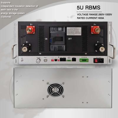
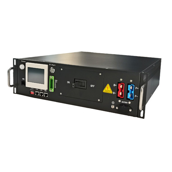
RBMS Interface Description
| No. | Name | Description | Precautions |
| 1 | B+ B- | Connect to the battery's total positive and total negative | Quick plug connection |
| 2 | P+ P- | Connect to the charging equipment (PCS) or DC bus | Quick plug connection |
| 3 | AC Input | The municipal power supply input port must be taken from the UPS/Inverter output side | 85~264VAC 1A max |
| 4 | ON OFF | ON: The circuit breaker is ON.
OFF: The circuit breaker is disconnected | When the handle of the circuit breaker is in the trip state in the middle position, it needs to be turned OFF before it can be closed again. |
| 5 | D1 D1 D2 D2 | Two dry contact output reserved | The default D1 is charging prohibited, D2 is discharging prohibited |
| 6 | Start | DC start button: start the RBMS system By taking power from the battery side. | The system is connected to the battery, and after the circuit breaker is closed, press and wait until the light is on to indicate
that the system is on |
| 7 | System | System status indicator | System normal: Green Alarm: yellow light Self test failure and protection status: red light
Charging: green light flashes
Discharge: red light flashing
Self checking: red and green flashing alternately
Pre-charging: yellow flashing |
| 8 | 1 2 4 8 | ID allocation: When multiple RBMS are
used in parallel, the ID are allocated by
setting the DIP switch. Must start at 1 | There are 4 DIP switches in total, supporting up to 15 RBMS in parallel
1 ON: ID+1
2 ON: ID+2
3 ON: ID+4
4 ON: ID+8 |
| 9 | TCP/IP | The RBMS host computer system software can be connected to the PC through the network cable | Network cable standard CAT5 or above, crossover cable or straight cable can be
used, the line sequence can be according
to the standard TIA-586A or TIA-568B |
| 10 | T-CAN
T-485 | Terminal matching resistance setting
during can and 485 communication
Setting Description: (120R), on is valid | In parallel application, only the last one needs to be set. In stand-alone application, it can be used flexibly according to site conditions (interference, communication distance, etc.). |
| 11 | COM-IN
COM-OUT | RBMS external communication port: When multiple RBMS in parallel: Communication with SBMS
When RBMS Stand-alone: communicate with UPS/PCS external devices | The shielded twisted-pair cable harness
must be used randomly. The cable
sequence is defined in the cable harness
label |
| 12 | GND
HMI-B
HMI-A
24V | 1.For external display connection
2.For powering SBMS | Please connect the display screen according to the silk screen sequence |
| 13 | BMU-OUT | Communication interface with BMU | Cascaded communication between BMU |
| 14 | ㊤ | RBMS chassis ground | Must be grounded, and the grounding
resistance is less than 1Ω |
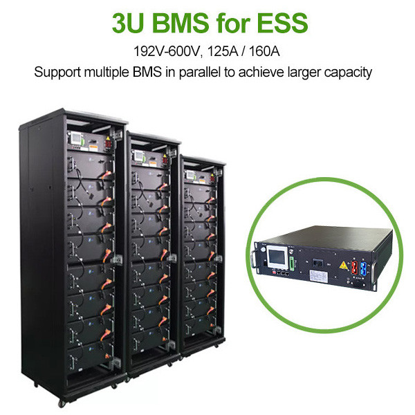
1024V 200Amp 4U RBMS
Communication protocol : Rs485,CAN, LAN
* 4U standard 19inch case
* Efficient, stable and reliable
* size:W485*H180*D550mm
Accessories
8S-24S BMU(Slave)
8S-24S BMU has 8pcs of tempreture sensors, Fan voltage 48V(17S-24S 12V), voltage detection range 0-5V,12V power supply,consumption less 20mA, CAN2.0 B communication
Wire harness-Signal acquisition wire
18 Pin+20Pin wire, standard length is 600mm,900mm,1200mmtempreture sensor. wire: standard length is 600mm,900mm,1200mm
Fan wire: 600mm
Wire harness-communication wire
Communication wire is connecting from master BMS to each BMU with cascade connection, the last port is for terminal resistance.wire: standard length is 180mm,300mm,600mm