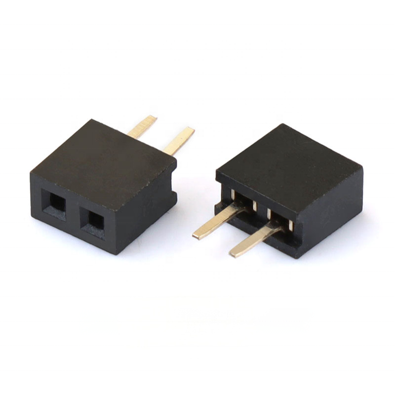
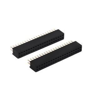
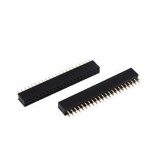
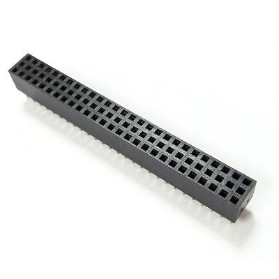
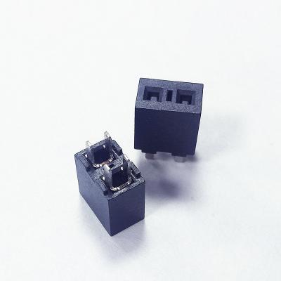
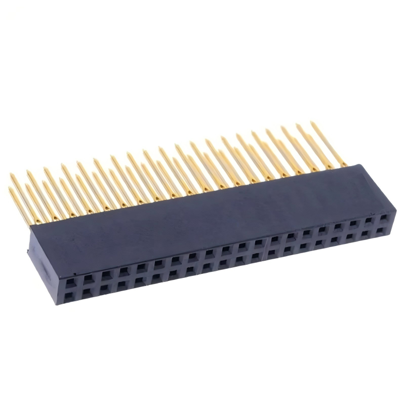
2mm 2pin Female Pin Header Vertical DIP Single Row 1*2P Female 2.0mm Pin Header Connector
Highlight
- 2.0 mm pitch, single‑row 2‑position vertical DIP through‑hole mounting, compact footprint for simple signal / low‑power jump connection
- Phosphor‑bronze spring contacts, stable gripping force, anti‑loosen under slight vibration conditions
- UL94V‑0 high‑temperature black insulator, compatible with standard wave‑soldering process
- Flexible plating options: tin/flash gold / selective gold; RoHS & REACH compliant for global OEM sourcing
- Drop‑in replacement for mainstream 2.0 mm pitch industry standard female header series, short lead‑time for mass production
Product Description
General Mechanical Parameters
| Item |
Specification |
| Product Type |
Female Pin Header (Socket) |
| Pitch |
2.0 mm |
| Pin Count |
2 Positions, Single Row |
| Mounting Type |
Vertical DIP / Through‑Hole |
| Mating Orientation |
Vertical straight insertion |
| Contact Material |
Phosphor Bronze |
| Insulator Material |
PBT UL94V‑0 Black |
| Mechanical Mating Cycles |
Min. 300 cycles |
| Insertion / Extraction Force |
0.6‑1.0 N per pin |
Material & Electrical Characteristics
| Item |
Specification |
| Contact Plating |
Tin / Nickel+Flash Gold / Selective Gold (customizable) |
| Rated Current |
1.5 A per pin |
| Rated Voltage |
AC 500 V |
| Contact Resistance |
Max. 20 mΩ (initial) |
| Insulation Resistance |
≥ 5000 MΩ |
| Dielectric Withstanding Voltage |
AC 500 V, 1 min no breakdown |
Environment & Soldering Guide
| Item |
Specification |
| Operating Temperature Range |
‑40 ℃ ~ +105 ℃ |
| Storage Temperature |
‑20 ℃ ~ +85 ℃ |
| Soldering Process |
Wave soldering recommended; Reflow condition max 260 ℃, 5‑10 s |
| Compliance |
RoHS, REACH |


Product Features
- Single row 2‑pin vertical straight DIP through‑hole design, simple 2‑line connection solution
- Phosphor‑bronze spring contact beam, consistent contact pressure, reduces intermittent signal risk under vibration
- Black high‑temperature UL94V‑0 plastic housing, resistant to soldering thermal shock, no melting or deformation during wave solder
- Multiple contact surface finishes optional: tin plating, nickel base with flash gold, selective gold plating for different cycle‑life requirements
- Standard footprint, directly compatible with mainstream 2.0 mm pitch male pin header mates
- RoHS‑compliant raw material, supports consumer & industrial finished‑product certification


Product Advantage
- DIP mechanical reliability: Through‑hole soldering provides far stronger PCB retention than SMT version; suitable for assemblies subject to plug‑unplug stress or minor vibration
- Targeted 2‑pin configuration: Optimized for power‑ground pair, simple trigger signal links; avoids redundant pins for minimal PCB space occupation
- Spring‑tuned phosphor‑bronze contact: Better contact stability than ordinary brass terminals; reduces field failure caused by poor contact in a vibration environment
- Cost‑flexible plating solution: Tin plating for mass‑cost‑sensitive consumer goods; flash / selective gold for industrial high‑mating‑cycle devices, no over‑spec cost waste
- Standard interoperability: Footprint and mating dimension follow industry‑wide 2.0 mm pitch norms, easy BOM substitution without PCB redesign
Application
- IoT sensor modules & wireless control units
- Embedded controller boards, auxiliary signal interfaces
- Household smart appliances, small control circuit boards
- Industrial auxiliary signal terminals, low‑power board‑jumper connection
- Test fixture, prototype development hardware

Customization Options
- Confirm mating part: must pair with 2.0 mm pitch single‑row male pin header; mismatched pitch will cause assembly damage and bad contact
- Mounting: choose this DIP vertical version when strong mechanical holding is required; switch to SMT variant if you need full surface‑mount assembly
- Plating selection:
- Tin plating: low‑cost consumer product, few mating cycles
- Nickel+Flash gold: industrial equipment, frequent plug‑in, humid operating environment
- Electrical derating: under continuous working & high‑ambient‑temperature condition, derate current to ≤ 70 % of rated value
- PCB footprint: strictly follow our dimension drawing; do not modify pad size arbitrarily to prevent cold solder or tomb‑stoning
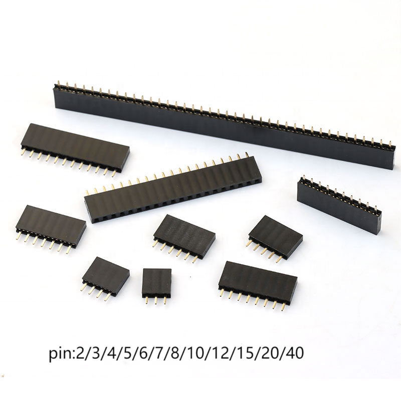
- If you need more positions, we support 1×3P‑1×40P single‑row female header customization

FAQ
Q: Can I get some samples?
A: Yes, some samples are free.
Q: Who do I contact if I have a technical question?
A: We have an experienced team of technical sales representatives in-house. They are ready to answer any questions you may have and assist you in your project.
Q: If defective products occur when receiving the goods, how to deal with it?
1. It's impossible for the goods not to be good as before shipping; we have many checks to confirm the products are no problem. Then, if happened, we will bear the responsibility.
2. First: why this will happen, how happen, and how to control it in the future; a table will come out for your checking.
3. Second: discuss the solutions.
4. Finally: we will bear all the fees if returning and changing the goods or the loss caused.
Q: How do you guarantee my goods right?
A: The order will be arranged exactly as requested; we will doubly check the packing and qty before delivering. Also, we will take photos of your goods if required or necessary.
Q: Which payment can be accepted:
1. The payment terms can be flexiable depend on the quantity and products.
2. Usually, for new customers, we prefer 100% T/T before shipping or 30%T/T advance before shipping.