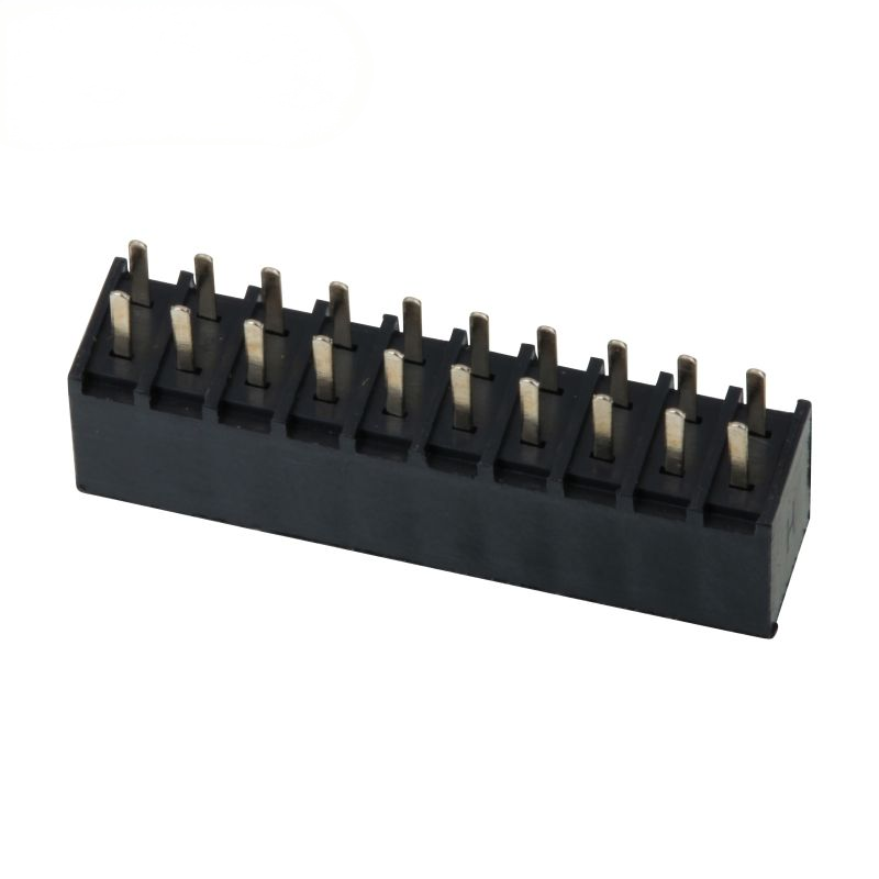
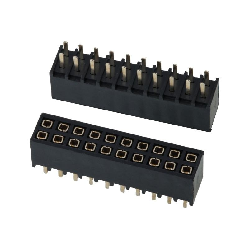
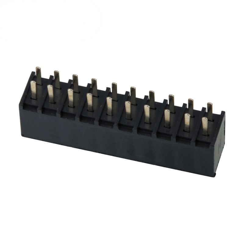
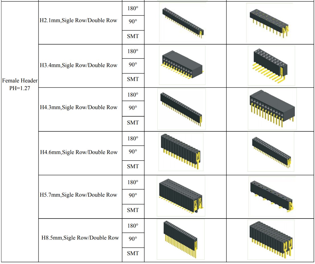
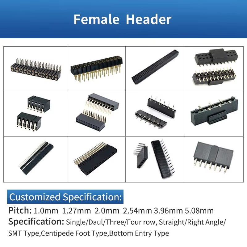
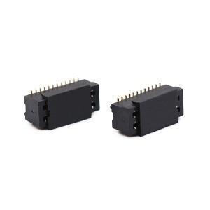
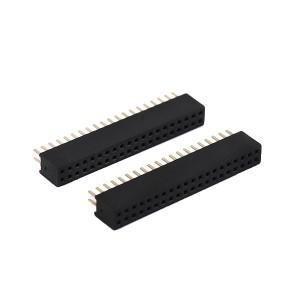
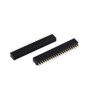
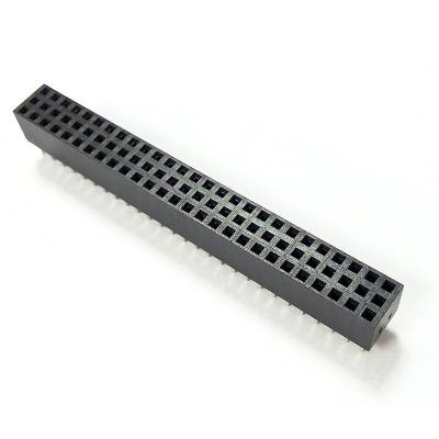
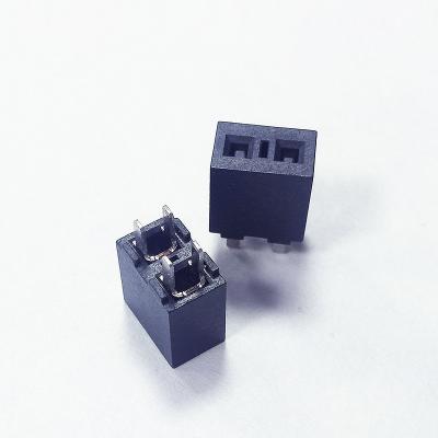
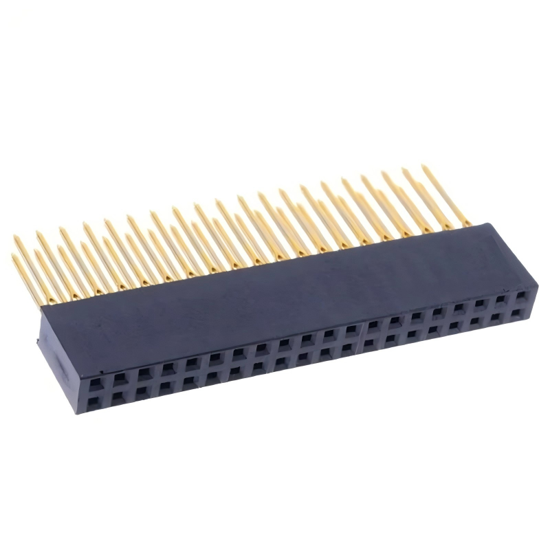
DIP Female Header 2.54 mm Pitch Double Row Female Straight Header Socket Pin Strip Connector
Highlight
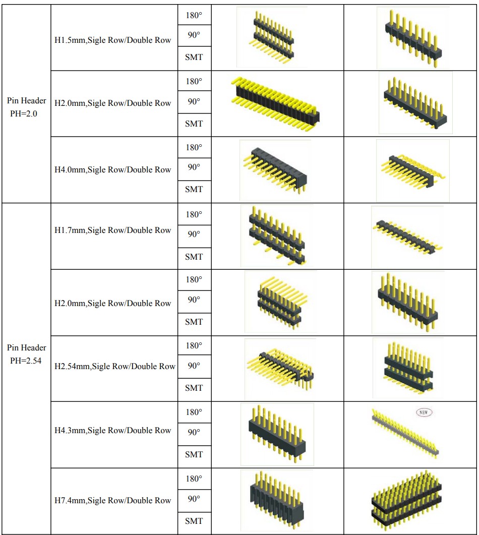
- Industry‑standard 2.54 mm (0.100") pitch double‑row DIP through‑hole female header, full interoperability with standard 2.54 mm male pin headers
- Phosphor‑bronze contact terminals, optional gold/tin plating, stable contact under vibration & frequent mating
- UL94‑V0 high‑temperature PBT housing, compatible with wave‑soldering & manual rework processes
- Wide pin‑count range 2×2P‑2×40P, custom pin‑tail / insulator height available for OEM projects
- RoHS & REACH compliant, cost‑effective board‑to‑board stacking & prototyping interconnect solution
Product Description
General Mechanical Parameters
| Item |
Specification |
| Product Type |
Double Row Straight DIP Female Header |
| Pitch |
2.54 mm (0.100 inch) |
| Row Spacing |
2.54 mm |
| Pin Count |
2×2P ~ 2×40P |
| Mounting Type |
DIP Through‑Hole |
| Standard Insulator Height |
8.5 mm |
| Standard PCB Tail Length |
3.2 mm |
| Mating Cycles |
500 cycles typical |
| Color |
Black |
Material & Electrical Characteristics
| Item |
Specification |
| Insulator Material |
PBT, UL94‑V0; optional PA66 / LCP |
| Contact Material |
Phosphor Bronze |
| Contact Plating |
Tin plating (std); Nickel + Gold plating (custom) |
| Rated Current |
3A per pin |
| Rated Voltage |
250 V AC/DC |
| Initial Contact Resistance |
≤20 mΩ |
| Insulation Resistance |
≥1000 MΩ @ DC 500 V |
| Dielectric Withstanding Voltage |
500 V AC for 1 min, no breakdown |
| Operating Temperature Range |
‑40 ℃ ~ +105 ℃ |
Environment & Soldering Guide
| Item |
Specification |
| Wave Soldering |
250 ℃, max 5 seconds |
| Manual Soldering |
300‑350 ℃, max 3 seconds per pin |
| Storage Condition |
‑10 ℃ ~ +40 ℃, 40‑70% RH, avoid corrosive gas |
| Compliance |
RoHS, REACH |


Product Features
- Double‑row straight vertical DIP through‑hole mounting, robust PCB mechanical anchoring against shock & vibration
- Standard 2.54 mm pitch, fully compatible with mainstream 2.54 mm male header footprints and off‑the‑shelf components
- Phosphor‑bronze spring contacts maintain consistent contact force over mating cycles, resist contact loosening
- Black PBT insulator UL94‑V0 flame retardant, withstands wave‑soldering thermal stress without deformation
- Flexible plating options: tin‑plated for general use; nickel‑under‑gold plating for harsh‑environment anti‑oxidation performance
- Pin‑count coverage: 2×2P up to 2×40P; custom pin‑tail length and housing height are supported
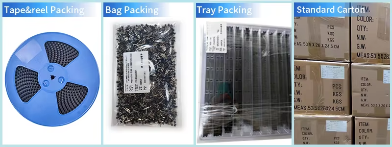
- RoHS/REACH compliant, supplied in bulk bag or box packing for high‑volume assembly


Product Advantage
- Strong PCB retention: DIP through‑hole soldering delivers far better mechanical stability than SMT headers for vibration‑prone equipment, preventing connector lifting off PCB.
- Full ecosystem compatibility: 2.54 mm industry standard pitch reduces component sourcing risk; drop‑in replacement for mainstream market equivalents.
- Dual‑row high‑density layout: Double‑row design packs more signal channels within shorter PCB footprint vs single‑row solutions, saves board space.
- Dual‑grade plating solution: Tin‑plated variant controls BOM cost for commercial‑grade products; gold‑plated option mitigates oxidation for outdoor / high‑humidity long‑life devices.
- Fast project iteration: Off‑the‑shelf standard pin counts for quick prototyping; custom dimensions available for OEM mass production.
- Assembly‑friendly: Insulator resists wave‑solder heat distortion, lower assembly reject rate on SMT / wave‑solder production lines.
Application
- Industrial control boards, PLC peripheral modules
- Embedded systems, single‑board computers, development boards
- IoT sensor gateways, smart home hardware
- Test & measurement equipment
- Robotics auxiliary control modules
- Automotive interior auxiliary electronics
- Medical non‑critical signal modules
- Consumer electronics, prototyping & DIY equipment

Customization Options
- Confirm pin configuration: Define total pin quantity (2×N), double‑row layout; verify matching male header pitch and row spacing strictly at 2.54 mm.
- Mounting check: Select DIP straight version when strong mechanical shock resistance is required; choose right‑angle variant if side‑mating is needed.
- Plating selection:
- Tin plating: indoor commercial devices, normal humidity environment, cost‑sensitive projects.
- Gold plating: outdoor, high‑humidity, long service‑life, frequent plug‑unplug scenarios.
- PCB footprint validation: Confirm PCB hole diameter matches DIP pin dimension; check insulator height to avoid mechanical interference with surrounding components.
- Thermal matching: If wave‑soldering process is applied, confirm insulator material meets soldering temperature requirement.
- Custom requirement: Submit drawing for non‑standard pin‑tail length, insulator height or special pin‑count.

FAQ
Q: Can I get some samples?
A: Yes, some samples are free.
Q: Who do I contact if I have a technical question?
A: We have an experienced team of technical sales representatives in-house. They are ready to answer any questions you may have and assist you in your project.
Q: If defective products occur when receiving the goods, how to deal with it?
1. It's impossible for the goods not to be good as before shipping; we have many checks to confirm the products are no problem. Then, if happened, we will bear the responsibility.
2. First: why this will happen, how happen, and how to control it in the future; a table will come out for your checking.
3. Second: discuss the solutions.
4. Finally: we will bear all the fees if returning and changing the goods or the loss caused.
Q: How do you guarantee my goods right?
A: The order will be arranged exactly as requested; we will doubly check the packing and qty before delivering. Also, we will take photos of your goods if required or necessary.
Q: Which payment can be accepted:
1. The payment terms can be flexiable depend on the quantity and products.
2. Usually, for new customers, we prefer 100% T/T before shipping or 30%T/T advance before shipping.