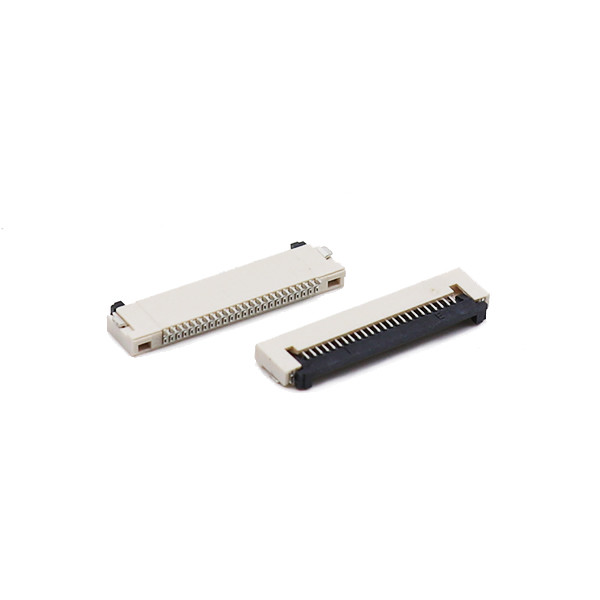
Vertical Type FFC FPC Connector Pitch 1.0mm Electrical Wire Connectors
Highlights
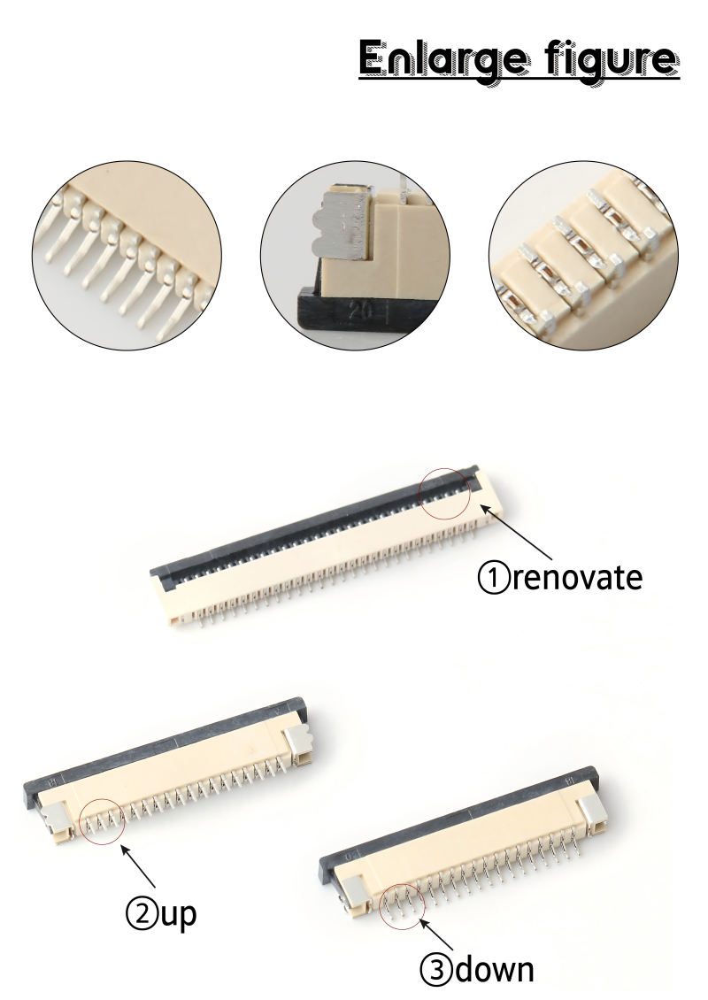
- Vertical top‑entry SMT FPC‑to‑board connector, 1.0 mm pitch, pin count configurable from 4 pins up to 50 pins.
- ZIF flip‑lock actuator design, low insertion force, robust cable retention against vibration & cable pull‑out.
- Phosphor‑bronze contact terminals, optional tin / selective gold plating for signal‑critical circuits
- Fully tape‑and‑reel packaged for high‑volume SMT automated assembly; compatible with standard pick‑and‑place equipment.
- RoHS 2.0 & REACH compliant; UL94‑V‑0 high‑temperature housing material for reflow soldering process
- Flexible customization: pin count, plating thickness, contact type, PCB footprint modification & OEM marking support
- Cost‑effective drop‑in alternative to major branded equivalents, short lead‑time for prototype & mass production orders
Description
| Pitch |
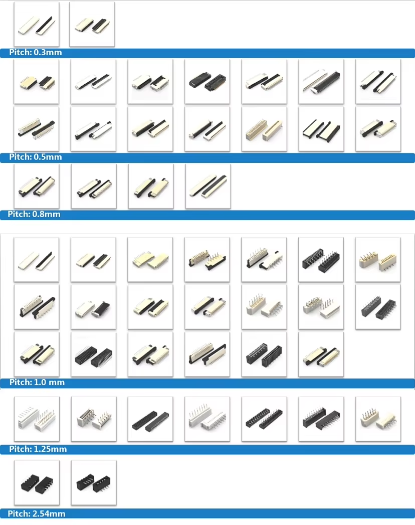
1.0mm |
| No. Of Positions |
4-50pin |
| Mounting Type |
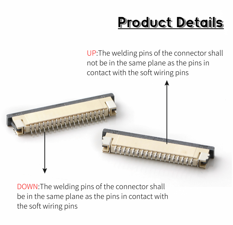
Vertical / ZIF |
| Contact Location |
Single-sided contact |
| Type |
Slide lock |
| Current Rating |
0.5A/Pin Max |
| Voltage Rating |
50V AC/DC MAX |
| Withstanding Voltage |
250V AC,1min |
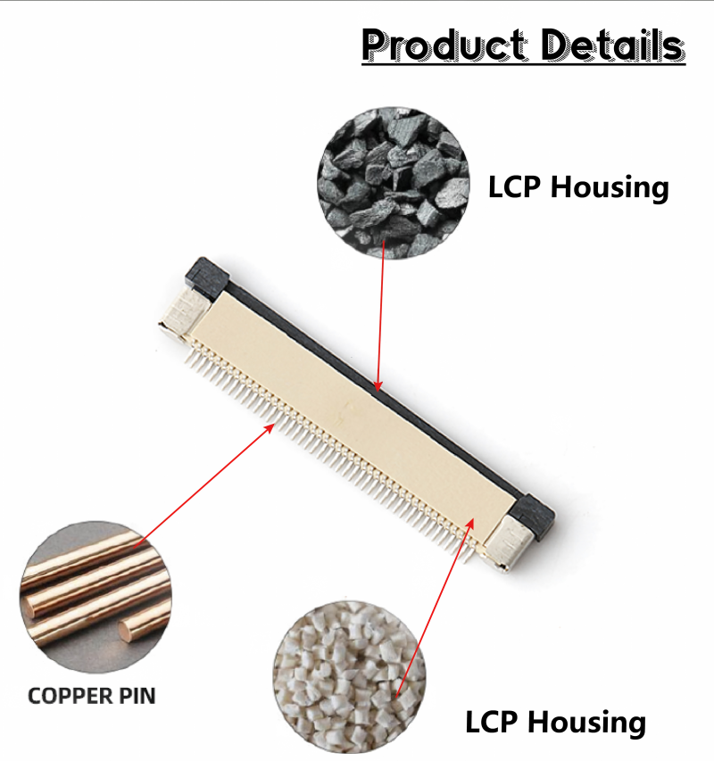
| Cover Material |
LCP UL94V-0 black |
| Housing |
LCP UL94V-0 Natural |
| Terminal/Contact |
Copper alloy |
| Plating |
Tin-plating |
| Operation Temperature |
-40℃ to +85℃ |
| Lead Time |
7-10 working Days |


Material & Electrical Characteristics
| Item |
Specification |
Remarks |
| Housing Material |
LCP / PA6T |
UL94‑V‑0 flame retardant |
| Actuator Material |
PPS / LCP |
High‑temperature resistant |
| Contact Terminal Material |
Phosphor Bronze |
High spring‑back performance |
| Plating Option‑1 |
Contact & Solder Tail: Matte Tin |
For general‑purpose signal |
| Plating Option‑2 |
Contact Area Selective Gold Plating (0.03‑0.1μm Au over Ni barrier) |
For high‑humidity / high‑vibration environment |
| Rated Current |
0.5 A per contact |
Signal‑level application |
| Rated Voltage |
50 V AC/DC |
Max working voltage |
| Contact Resistance |
≤30 mΩ (initial) |
After mating under test conditions |
| Insulation Resistance |
≥500 MΩ |
DC 100 V testing |
| Withstand Voltage |
500 V AC / 1 minute |
No breakdown / flash‑over |
Design &Technical strength
We have more than 20 years of experience in the connector industry; our engineers can support your new project. Design a new tooling time:30-45 working days.
Competitive Advantage
Keyouda has various types of appearance and many kinds of internal schematic products, high quality, customer first,100% test, 0 defects, and short lead time are our best advantages
Target Application Industries
- Consumer Electronics: Display modules, POS terminals, household appliances, smart home panels, portable handheld devices
- Industrial Control: Human‑machine interface HMI, sensor modules, industrial display, test‑measurement equipment
- IoT & Smart Hardware: Gateway devices, surveillance cameras, drone peripheral modules, smart lighting control
- Medical Equipment: Patient monitoring auxiliary modules, non‑critical signal interconnection for medical devices
- Peripheral Equipment: Printer modules, scanner internal interconnects, small‑size LCD panel driver boards
FAQ
Q1: Can this connector work with both FPC rigid‑flex and standard FFC flat cables?
A1: Yes. It supports both 0.3 mm‑thickness FPC and matching FFC flat cables. Please make sure conductor pad orientation matches the contact side of the connector.
Q2: What will happen if I use an FPC thicker than 0.33 mm?
A2: An over-thick flex cable will prevent the flip‑lock actuator from fully closing, causing insufficient contact pressure and an increased risk of intermittent connection. Strictly follow the recommended flex thickness.
Q3: Is this connector automotive grade?
A3: Standard version is for consumer & general‑industrial use. For automotive applications, please contact our sales team for an automotive‑grade modified variant with enhanced material & test standards.
Q4: Can I hand‑solder this connector instead of SMT reflow?
A4: Hand‑soldering is allowed for prototype debugging only. Do not apply heat to plastic housing; limit single‑pin soldering time to under 5 seconds. Hand‑soldering is NOT recommended for mass production.
Q5: What is the difference between front‑flip and back‑flip ZIF actuator?
A5: Front‑flip: latch sits on FPC insertion side, easy manual operation. Back‑flip: latch is located opposite the insertion side, delivers superior cable retention force for a vibration‑heavy environment.
Q6: Can you modify the PCB footprint for our existing old‑design replacement project?
A6: Yes, footprint modification service is available. Please provide your original PCB drawing; our engineering team will evaluate feasibility and NRE cost.
Q7: What is MOQ and sample lead‑time?
A7: Free engineering samples available; sample lead‑time 1‑3 working days. Mass‑production MOQ depends on configuration; tape‑and‑reel standard parts support low‑MOQ orders.