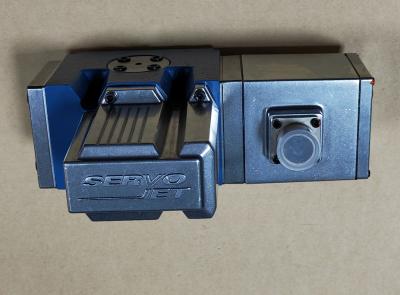
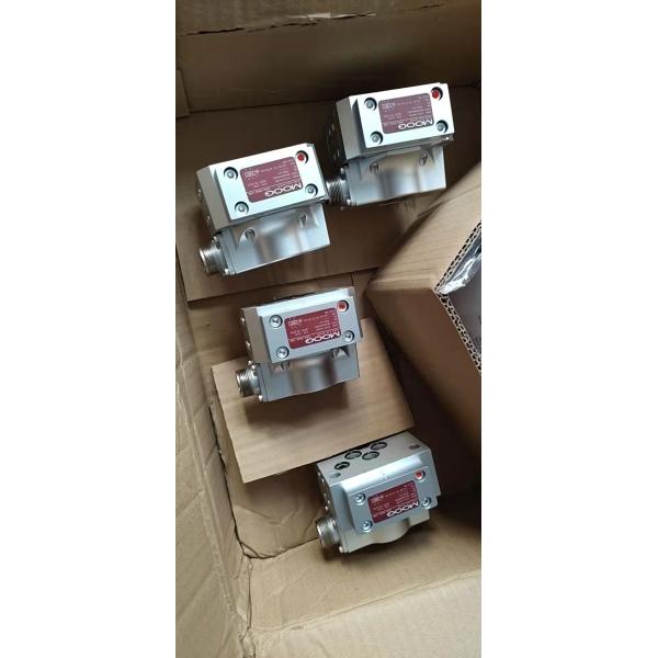
D633-471B D633-472B
D633-473B D633-481B
D633-525B D634-538A
D661-393D D661-4023
D661-4033 D661-4070 German made MOOG servo valve
| rated current | 1A | voltage | 24V 220v |
| power | 0.1 kW | model | D633-471B D633-472B D633-473B D633-481B D633-525B D634-538A D661-393D D661-4023 D661-4033 D661-4070 |
| brand | MOOG | place of origin | Germany |
| application | LED touch control | material | PVC, Steel, copper |
| rated frequency | 50 Hz | brand | Muge |
| type | Servo proportional valve | control | Electro hydraulic/Proportional |
| material | Advanced alloy steel/cast iron |

| Original MOOG D651-471 |
| Original MOOG D651-471D |
| Original MOOG D653-2709E |
| Original MOOG D656Z130 |
| Original MOOG D661 UNIDENTIFIED |
| Original MOOG D661-1062E |
| Original MOOG D661-1718 |
| Original MOOG D661-1962E |
| Original MOOG D661-2057 |
| Original MOOG D661-205A |
| Original MOOG D661-318A |
| Original MOOG D661-363 |
| Original MOOG D661-363A |
| Original MOOG D661-363D |
| Original MOOG D661-3702E |
| Original MOOG D661-4020B |
| Original MOOG D661-423A |
| Original MOOG D661-4491E |
| Original MOOG D661-450C |
| Original MOOG D661-450D-4 |
| Original MOOG D661-473B |
| Original MOOG D661-4744 |
| Original MOOG D661-4793 |
| Original MOOG D661-515A |
| Original MOOG D661-5718 |
| Original MOOG D661-5729 |
| Original MOOG D661Z1718F |
| Original MOOG D661Z2742F |
| Original MOOG D661Z2743H |
| Original MOOG D661Z3726E |
| Original MOOG D661Z5604 |
| Original MOOG D661Z6716 |
| Original MOOG D661Z671C |
| Original MOOG D661Z736A |
| Original MOOG D662-1714G |
| Original MOOG D662-1942E |
| Original MOOG D662-2714E |
| Original MOOG D662-4348K |
| Original MOOG D662-5704 |
| Original MOOG D662-580A |
| Original MOOG D662-5NC |
| Original MOOG D662-Z917G |
| Original MOOG D662E957A |
| Original MOOG D662Z4719B |
| Original MOOG D662Z902B |
| Original MOOG D663-1902E |
| Original MOOG D663-2709E |
| Original MOOG D663-344C |
FAQ:
How does a Moog Servo Valve work?
A Moog servo valve typically consists of a polarized electrical torque motor and a two-stage hydraulic amplifier .
• First Stage: The torque motor deflects an armature and a flapper attached to it. This flapper moves between two nozzles, creating variable orifices that control the pressure on either end of the second-stage spool .
• Second Stage: The differential pressure moves the spool, which then controls the flow of hydraulic fluid to the actuator. A feedback spring, connected to the flapper and engaging the spool, creates a force that balances the input signal torque, ensuring precise spool positioning proportional to the electrical command .
3. What are the key installation requirements?
Proper installation is critical for performance and longevity.
• Filtration: Install a precision filter with a rating of 5 microns or less upstream of the servo valve. The hydraulic fluid cleanliness should be maintained at a maximum ISO DIS 4406 Code 16/13, with Code 14/11 recommended .
• System Flushing: Before installing the servo valve, the entire hydraulic system must be thoroughly flushed to remove contaminants. Use a flushing manifold and circulate fluid under conditions simulating normal operation .
• Mounting: The valve can be mounted in any orientation, ensuring port alignments match the manifold. The mounting surface should be clean, smooth, and flat. Use the specified screws and torque them to 96 inch-pounds .
• Connections: Use O-ring seal connections (e.g., SAE J1926) and avoid welded fittings. Prefer crimped or 24-degree cone type connections .
4. What are common faults and how can I troubleshoot them?
Common faults can be categorized as follows :
• Electrical Faults: Include power supply failure, cable damage, or poor contact. Check the supply voltage, cables, and connectors.
• Mechanical Failures: Such as a stuck valve spool, damaged springs, or worn seals. Regular inspection, cleaning, lubrication, and part replacement are necessary.
• Hydraulic Faults: Including oil contamination, low oil level, or oil leaks. Regularly replace and filter the oil, check oil levels, and repair leaks.
• Valve Oscillation: Unstable operation may be caused by issues with the servo valve's resolution, wear of the valve port, or incorrect control system parameters.
Here is a brief troubleshooting chart based on symptoms :
Potential Trouble Probable Cause
Servovalve does not follow input command 1. Open coil or coil leads.
2. Clogged inlet filter.
Poor response 1. Clogged inlet orifices or nozzles.
2. Partially clogged filter.
3. "Sticky" spool.
No response to electrical signal Shorted coil assembly.
Low flow gain 1. Incorrect null adjustment.
2. Partially plugged orifice or filter.
5. What does daily maintenance involve?
Routine maintenance focuses on preventing common faults :
• Hydraulic Fluid: Maintain the recommended cleanliness level. Change the oil regularly (e.g., every six months) and keep the oil temperature within the 40°C to 50°C range.
• Filters: Monitor the pressure drop across filters and replace elements periodically or when the pressure drop becomes excessive.
• General Inspection: Regularly check for oil leaks, inspect the valve for unusual noises or vibrations, and ensure electrical connections are secure.