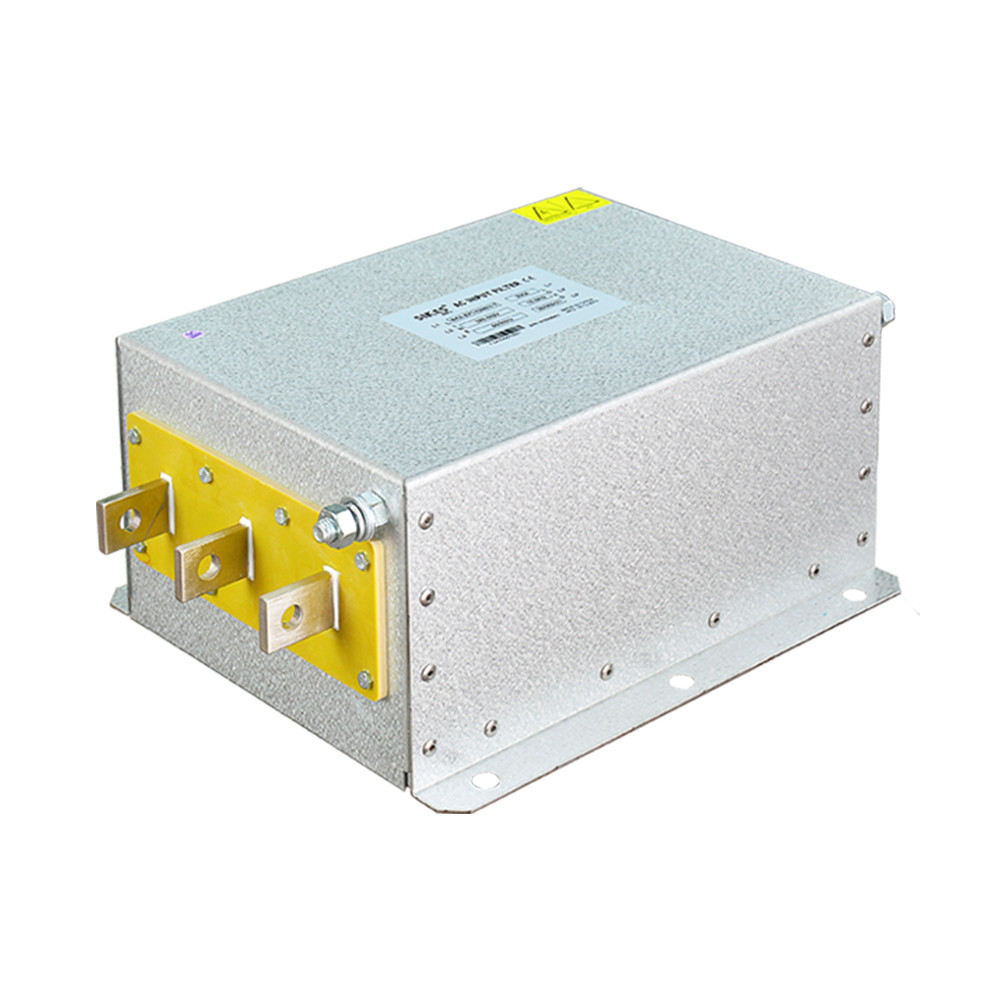
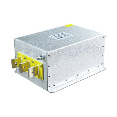
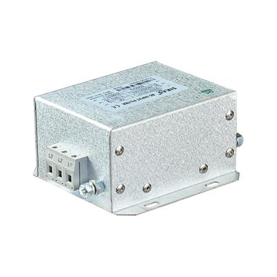
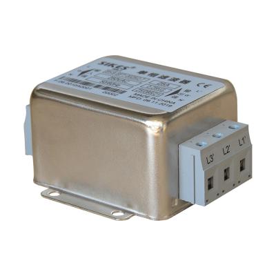
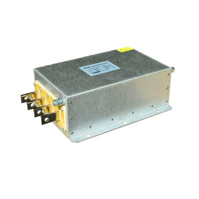
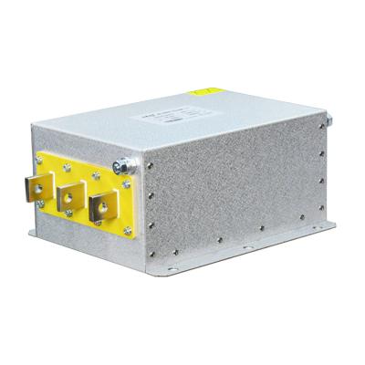
380v Three Phase AC EMI Filter electromagnetic interference filter
   
  EMI Power Line Filter from the LC low-pass passive network components.It uses principles of impedance mismatch,so that by
  the attenuation of electromagnetic interference signals.
  Filter filtering effect depends on the extent of impedance mismatch,the greater the impedance difference, the better the
  filter. For example,to get better results, for low-impedance power supply side, should be accompanied by a high input
  impedance of the filter;pairs of high input impedance of the load side, then the filter with low output impedance.
   
  Product Features
   
  This catefory of products has superior capability of interference containment and can be applied to data processing system, telecommunication equipment inverter and power conditioning equipment that impose high requirement on interference containment.
   
  Rataed Voltage: AC 380V-440V
  Test Voltage (1minute): Phase to Phase DC 1500V; Phase to Ground AC 1500V / DC 2500V
  Operating Frequency: 50/60HZ
  Range of temperature: -25-85℃
  Insulation Resistance: Phase to ground (up to 300A) ≥ 1500MΩ
   
   
   	 		 			| Model |  			Low Pass EMI Filter  |  		
 		 			| Transfer Function |  			Low Pass |  		
 		 			| Package Type |  			Surface Mount |  		
 		 			| Nominal Center Frequency |  			10K-30MHZ |  		
 		 			| Insertion Loss |  			60~90dB |  		
 		 			| Input Impedance |  			50Ω |  		
 		 			| Rated Voltage |  			380V/440V |  		
 		 			| Rated Current |  			1A-100A |  		
 		 			| Environmental Temperature |  			40°C |  		
 		 			| Temperature Range |  			25 / 085 / 21 |  		
 		 			| Operating Frequency |  			50/60HZ |  		
 		 			| Line to Line |  			1450VDC |  		
 		 			| Line to Ground |  			2250VDC or 2000VAC |  		
 		 			| Maximum Leakage Current |  			115VAC/60HZ 1.4mA Max. 250VAC/60HZ 2.5mA Max |  		
 		 			| MOQ |  			5pcs |  		
 		 			| Price |  			USD60~80/Meter |  		
 		 			| Lead Time |  			5~15 weekday for Low Pass EMI Filter |  		


  Filter instructions
   
   Consider the selection of the main filter insertion loss,the manufacturer of the given curve (parameters) in general in the
  standard 50-system test results are only for reference, but the actual applications are generally not 50 systems, insertion loss will
  be some offset.
  Filter selected second point to note are: operating voltage, operating current, voltage value, leakage current, dimensions,
  installation methods; special requirements and special applications must be described when ordering.
  DIN-type security choice of terminals: DIN security terminal has the following features: touch security; internal solid, has great
  access to cross-sectional area;in line with European industry standards,than conventional terminals safer and more convenient;
  use of DIN terminal of the filter is more in line with European market requirements. Most of the products of SIKES to support the
  kinds of terminal mode.


  Insertion loss
   Insertion loss (IL) is the ratio that filter access port voltage of the circuit before and after, be expressed with the following:
  Insertion loss (IL) = 20LgV1/V2
  Where: V1- the interference signal voltage before filter access
  V2- the interference signal voltage after filter access
  Insertion loss test methods are detailed in the CISPR17 requirements. In general, product samples provided on the insertion
  loss curve is obtained in the 50Ω system: the assumption on both sides of the output power and load, input impedance is
  resistive to 50Ω. As the actual use of the environment in the power side and load side of the impedance vary greatly, so
  when you get the actual use of the insertion loss values and the samples of different nominal values of insertion loss.
  Therefore, the selection of EMI power filter is the best way to access equipment that it carried out the actual tests