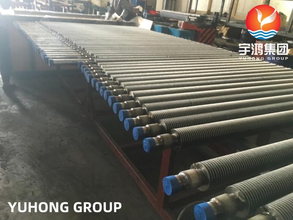
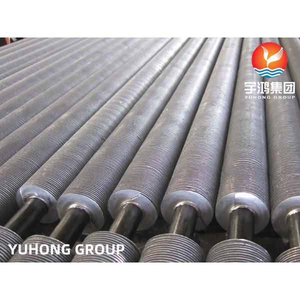
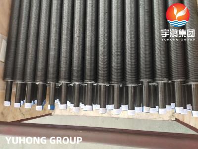
HFW Finned Tube ASTM A213 T12 Alloy Stainless Steel Base Tube TP304 Fins for Power Plant
This welded steel finned tube configuration can be used in virtually any heat exchanger application and is particularly suitable for high temperature and high pressure applications. The important features of this configuration are the efficient and effective connection of the fin to the tube under all temperature and pressure conditions and the ability to withstand high temperatures on the fin side.
A continuous helical fin is attached to the base tube by means of high-frequency electrical resistance welding in order to provide an efficient and thermally reliable connection.
Main chemical composition(%)
Grade | UNS Designation | C | Mn | P | S | Si |
T2 | K11547 | 0.10–0.20 | 0.30–0.61 | 0.025 | 0.025B | 0.10–0.30 |
T5 | K41545 | 0.15 | 0.30–0.60 | 0.025 | 0.025 | 0.5 |
T5b | K51545 | 0.15 | 0.30–0.60 | 0.025 | 0.025 | 1.00–2.00 |
T5c | K41245 | 0.12 | 0.30–0.60 | 0.025 | 0.025 | 0.5 |
T9 | K90941 | 0.15 | 0.30–0.60 | 0.025 | 0.025 | 0.25–1.00 |
T11 | K11597 | 0.05–0.15 | 0.30–0.60 | 0.025 | 0.025 | 0.50–1.00 |
T12 | K11562 | 0.05–0.15 | 0.30–0.61 | 0.025 | 0.025B | 0.5 |
T17 | K12047 | 0.15–0.25 | 0.30–0.61 | 0.025 | 0.025 | 0.15–0.35 |
T21 | K31545 | 0.05–0.15 | 0.30–0.60 | 0.025 | 0.025 | 0.50–1.00 |
T22 | K21590 | 0.05–0.15 | 0.30–0.60 | 0.025 | 0.025 | 0.5 |
T23 | K40712 | 0.04–0.10 | 0.10–0.60 | 0.03 | 0.01 | 0.5 |
T24 | K30736 | 0.05–0.10 | 0.30–0.70 | 0.02 | 0.01 | 0.15–0.45 |
T36 | K21001 | 0.10–0.17 | 0.80–1.20 | 0.03 | 0.025 | 0.25–0.50 |
T91 | K90901 | 0.07–0.14 | 0.30–0.60 | 0.02 | 0.01 | 0.20–0.50 |
T92 | K92460 | 0.07–0.13 | 0.30–0.60 | 0.02 | 0.01 | 0.5 |
T122 | K91271 | 0.07–0.14 | 0.7 | 0.02 | 0.01 | 0.5 |
T911 | K91061 | 0.09–0.13 | 0.30–0.60 | 0.02 | 0.01 | 0.10–0.50 |
Manufacturing Process of HFW Fin Tubes
1. Raw Material Preparation
Choose base tubes of appropriate materials and specifications, according to application scenarios and performance requirements. Ensure they possess good mechanical properties and corrosion resistance.
Fin materials usually include alloy, carbon steel, stainless steel. Carbon steel fins have low cost and are suitable for general industrial occasions; stainless steel fins perform well in environments with high corrosion resistance requirements. The shape and size of fins also need to be determined according to design requirements.
2. Fin Forming
Blanking Method: Use a punch and die to blank the fin material into the required shape and size.
Rolling Method: Continuously roll metal strips into fin shapes through special rolling equipment.
3. High - Frequency Welding (HFW)
(1).Positioning of Base Tube and Fins
Convey the prepared base tube to the welding station through a feeding device, and at the same time, accurately sleeve the fins on the base tube at a certain spacing and angle.
(2).High - Frequency Induction Heating
Use a high - frequency induction coil to heat the contact part of the base tube and fins.
(3).Pressure Application for Welding
While heating, apply a certain pressure to the fins through a mechanical device to make the fins closely contact the base tube.
4. Cut - to - Length
According to actual usage requirements, cut the welded fin tubes into specified lengths using cutting equipment.
5. Surface Treatment (Optional)
- Rust Prevention Treatment
- Anti - Corrosion Treatment
6. Quality Inspection
- Visual Inspection
- Dimensional Inspection
- Performance Inspection