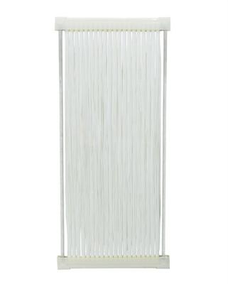
UF System Safe and Stable Operation Guide for MBR Membrane Element Operation SNU-HO-2-C1060
-
MBR MEMBRANE PVDF-8/PVDF-10/PVDF-15/PVDF-20
MBR Membrane membrane series: In the condition of high pressure, high hydrophilia and high flux, more improvements are made on membrane's polluting resistance and longer life-time. The Hollow Fiber Membrane MBRs' compact structure design occupies much less space, with easy installation.It is used for municipal and industrial waste water treatment. Fiber Membrane Mbr Bioreactor solves problem of the leakage of SS compared with traditional activated sludge sedimentation process, and prevent microorganism like colibacillus and cryptosporidium from water output.
Product working principle
The list of a full MBR plant
Advantages of MBR System
The advantages of MBR systems over conventional biological systems include better effluent quality, smaller space requirements,and ease of automation. Specifically, MBRs operate at higher volumetric loading rates which result in lower hydraulic retention times. The low retention times mean that less space is required compared to a conventional system. The effluent from MBRs contains low concentrations of bacteria, total suspended solids (TSS), biochemical oxygen demand (BOD), and phosphorus. This facilitates high-level disinfection. Effluents are readily discharged to surface streams or can be sold for reuse, such as irrigtion
| |
| | |
| | |
| | |
NACIO Cleaning Concentration | |
| | |
| | |
| | |
| | |
| | |
| | |
Max Transmembrane Pressure | |
| | Intermittent Permeate, Continuing Aeration |
| | |
| | |
| | |
| | |
| Remark: The actual permeate and back wash flux depends on the whole system's operation and maintenance: The output water parameter may varify a bit according to feed water conditions. |
| | | | |
| | | | |
| | | | |
| | | | |
| | | | |
| | | | |
| | | | |
| | | | |
| | |
Aeration (air-water ratio) | |
Note: 1. PVDF-10 or PVDF-15 membrane assemblies are taken as examples in the design table. 2. The size of the membrane module in the table is the recommended data, which can be adjusted according to the site conditions; 3. The water production value in the table is the recommended under common sewage treatment conditions. Users should adjust the value according to the actual situation of sewage, such as COD , MLSS, Aeration rate, etc. |
UF Specifications and Models
| Model | Membrane Material | Operation Mode | Membrane Element Size (mm) | Effective Membrane Area (m²) | Nominal Filter Pore Size (μm) |
| SNU-HI-1-C1030 | PES | inside-out | Φ250×965 | 23 | 0.01 |