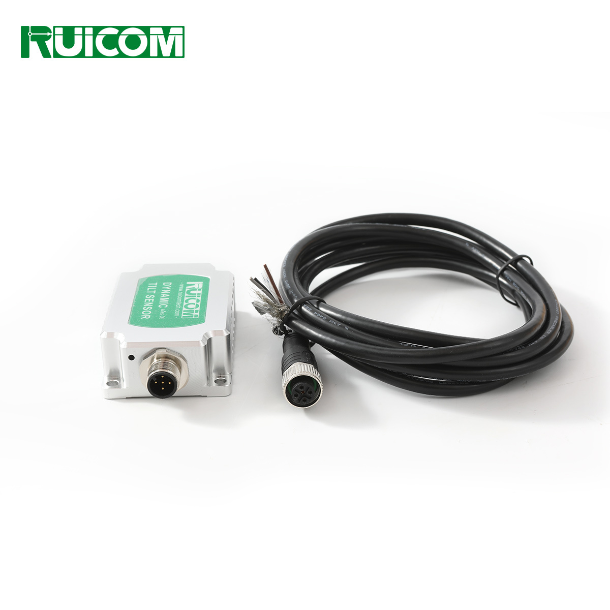
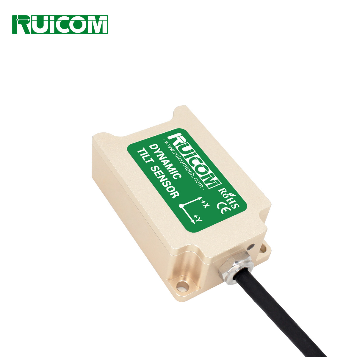
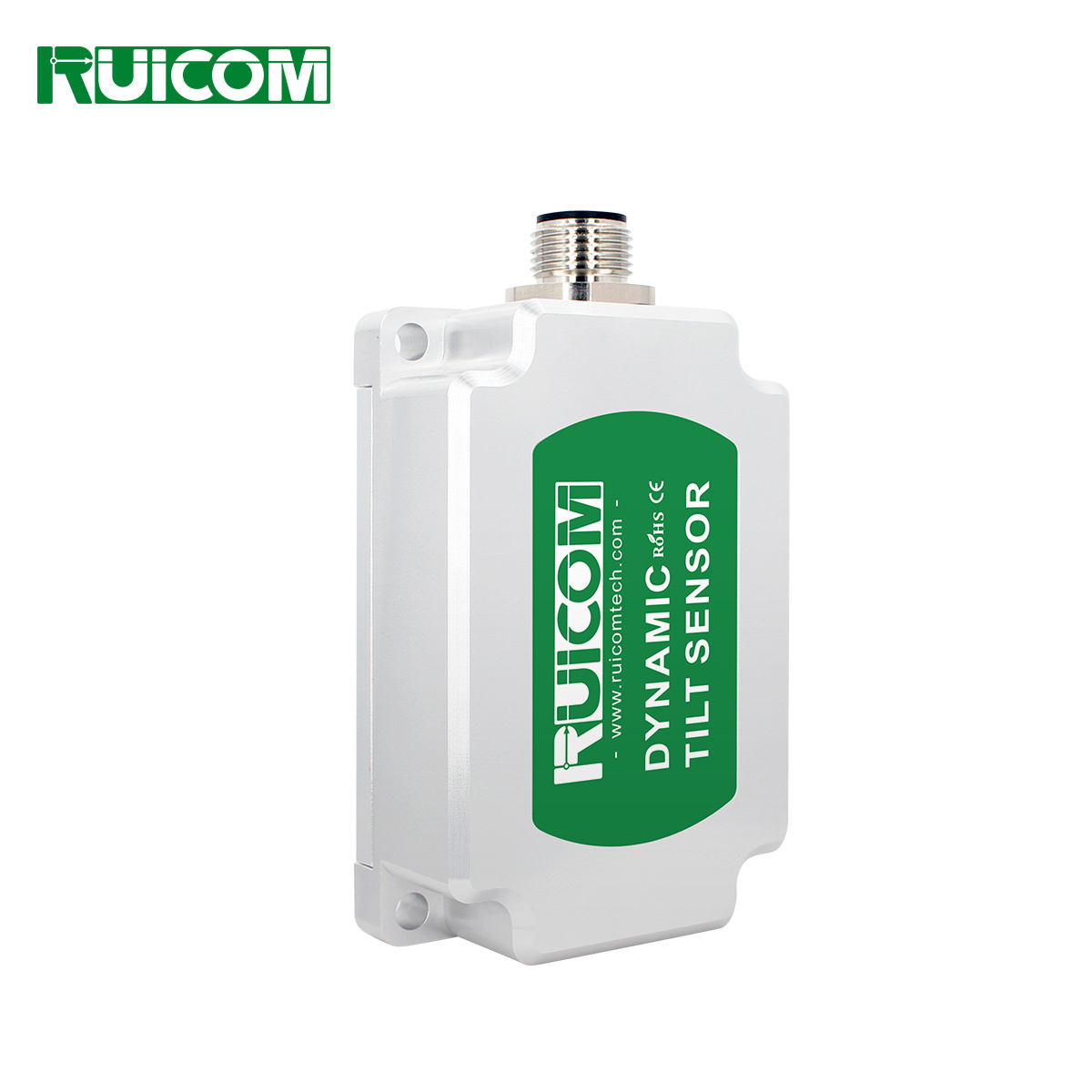
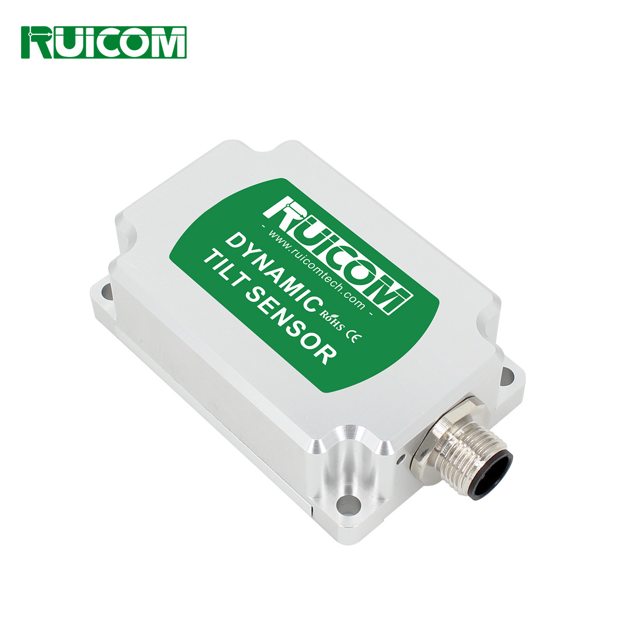
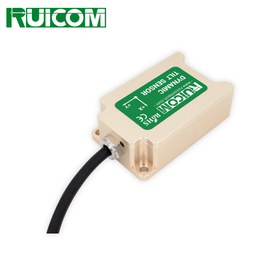
The DTS CAN2.0 A/B is a high-precision digital dynamic tilt sensor developed by RUICOM Technology based on advanced MEMS technology. It is specifically designed for real-time attitude monitoring of moving vehicles, accurately measuring roll, pitch, and azimuth angles, and is particularly suitable for attitude analysis in highly dynamic or strong vibration environments. This product adopts a dual CAN bus architecture (supporting CAN2.0A/CAN2.0B protocols), possessing excellent system compatibility and scalability.
Its core features include:
1) Multi-axis inertial measurement unit: Integrating a high-precision three-axis accelerometer and gyroscope, combined with an adaptive Kalman filter algorithm, to achieve real-time attitude calculation under motion conditions.
2) Dynamic compensation technology: Built-in high-resolution AD and six-axis IMU, real-time correction of nonlinear errors, axial coupling, temperature drift, and rotational centrifugal force interference, effectively suppressing the influence of motion acceleration on the measurement and ensuring dynamic accuracy.
3) Industrial-grade reliability: Supports wide operating temperature range of -40℃ to +85℃, with high shock resistance, high vibration resistance, and anti-interference capabilities, suitable for harsh industrial scenarios such as engineering machinery and special vehicles.
Its technical advantages include:
1) Non-contact measurement: No mechanical calibration required, easy installation, and direct output of digital attitude data.
2) Dual CAN redundancy design: Enhances system compatibility and supports multi-node networking requirements in industrial automation.
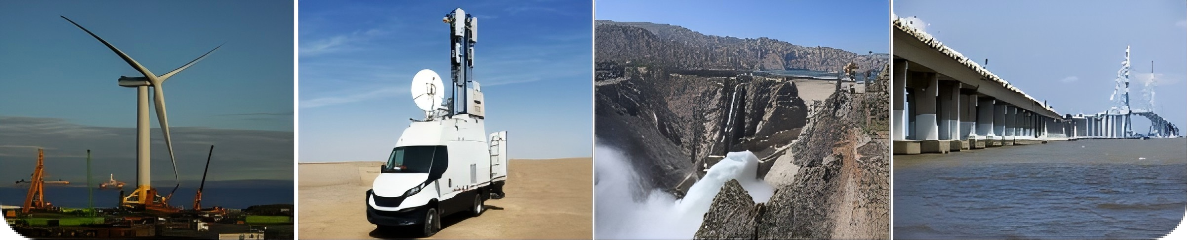
3) Dual-mode output (static and dynamic): Balances high static stability with high dynamic responsiveness, adapting to complex working conditions: high-precision industrial automation fields such as engineering machinery leveling, AGV navigation, ship attitude control, and aerospace attitude measurement.
Technical Characteristics
★ Measuring Range (R±180°, P±90°, Y±180°)
★ Dynamic Accuracy ±0.1°
★ Static Accuracy ±0.05°
★ CAN2.0A/B Optional
★ Three Protection Classes Available
Application Field
★ High-impact vibration crushing equipment
★ Aircraft attitude control
★ Construction equipment leveling
★ Ship attitude monitoring
★ Agricultural machinery monitoring and control
★ Engineering vehicle equipment monitoring and control

Performance Parameters
|
DTS CAN2.0 A/B |
Parameter |
|
|
Measurement Range |
Roll ±180°, Pitch ±90°, Azimuth ±180° |
|
|
(Initial value after power failure is 0°) |
||
|
Measurement Axis |
X-axis / Y-axis / Z-axis |
|
|
Roll and Pitch Resolution1) |
0.01° |
|
|
Roll and Pitch Static Accuracy @25℃ |
±0.05° |
|
|
Roll and Pitch Dynamic Accuracy (RMS) @25℃ |
±0.1° |
|
|
Gyroscope |
Gyroscope Range |
±300°/s |
|
Zero bias stability (10s smooth) |
8.5°/h |
|
|
Oblique Instability (Allan) |
4.5°/h |
|
|
Angle random walk coefficient(Allan) |
0.25°/sqrt(h) |
|
|
Acceleration |
Acceleration Range |
±4g / ±16g(optional) |
|
Zero bias stability (10s smooth) |
0.02mg |
|
|
Oblique Instability (Allan) |
0.005mg |
|
|
Angle random walk coefficient(Allan) |
0.005m/s/sqrt(h) |
|
|
Zero-point temp coefficient3)@-40~85℃ |
±0.01°/℃ |
|
|
Sensitivity temp coefficient4)@-40~85℃ |
≤100ppm/℃ |
|
|
Power-on time |
≤3.5S |
|
|
Response time |
0.01S |
|
|
Communication protocol |
CAN2.0A/CAN2.0B |
|
|
Electromagnetic compatibility |
According to EN61000 and GBT17626 |
|
|
Insulation resistance |
≥100megaohm |
|
|
Shock resistance |
100g@11ms, triaxial (half-sine wave) |
|
|
Vibration resistance |
10grms / 10~1000Hz |
|
|
Protection class |
IP67 / IP68 / Anti-corrosion (optional) |
|
|
Connector/cable |
M12-5-pin aviation plug connector / |
|
|
Weight |
Single connector ≤176g / |
|
|
1) Resolution: The smallest angular change that the sensor can detect within its effective range, reflecting its ability to monitor minute tilt fluctuations. |
||
Electrical Parameters
|
Parameter |
Condition |
MIN |
TYP |
MAX |
Unit |
|
|
Power supply voltage |
Standard |
9 |
12 |
24 |
36 |
V |
|
Operating current |
No load |
|
40mA(12V) |
|
mA |
|
|
Operating temp |
|
-40 |
|
85 |
℃ |
|
|
Storage temp |
|
-40 |
|
85 |
℃ |
|
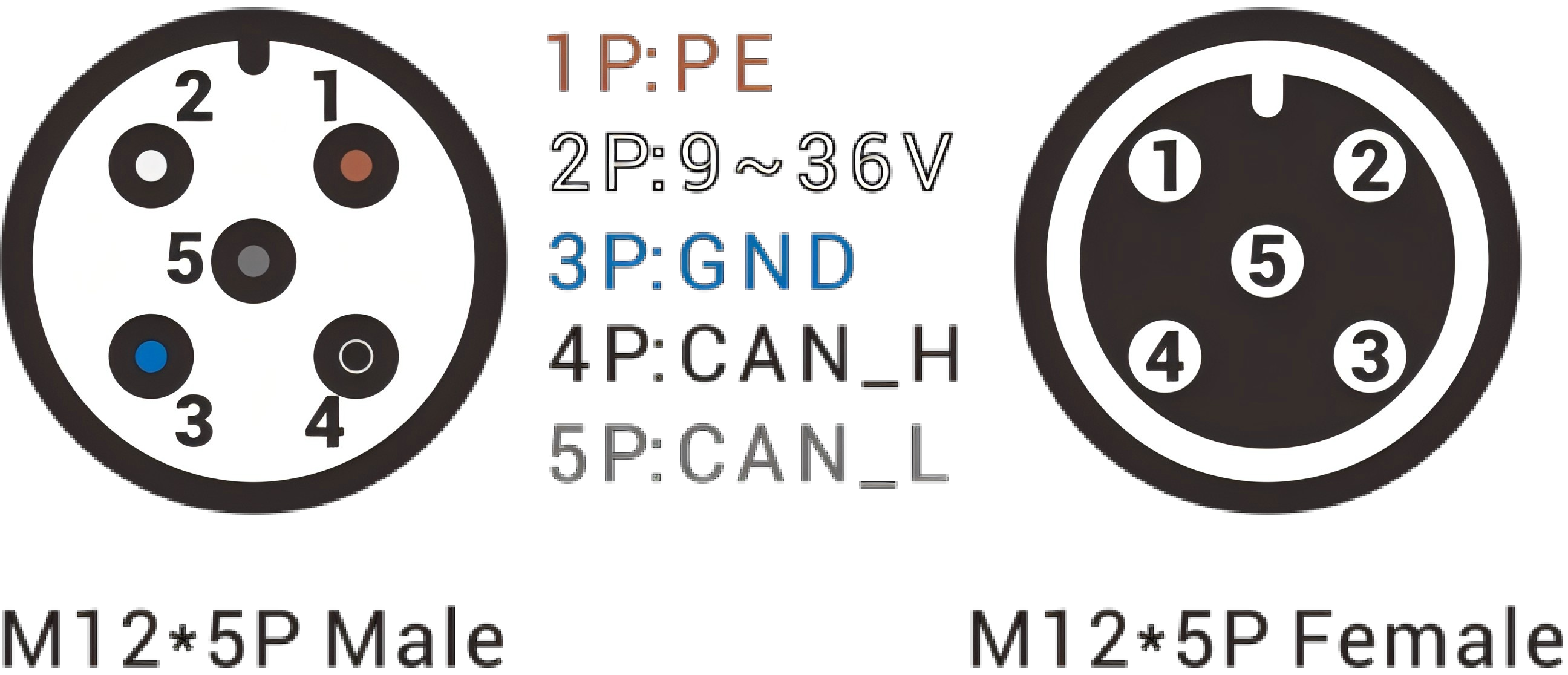
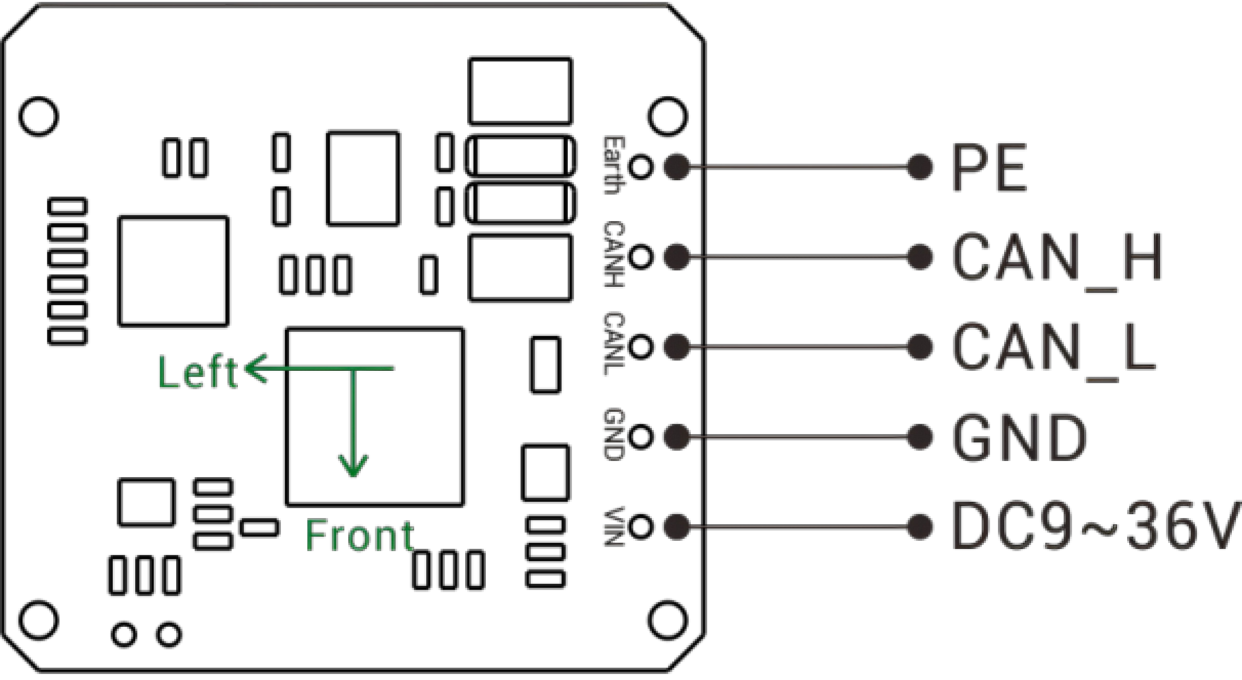
Interface Definition
|
PIN/Thread Color |
Definition |
Description |
|
PIN1 / Brown |
PE |
Protective ground |
|
PIN2 / White |
9~36V |
Positive power supply |
|
PIN3 / Blue |
GND |
Negative power supply |
|
PIN4 / Black |
CAN_H |
- |
|
PIN5 / Gray |
CAN_L |
- |
Connector pin definition diagram PCBA board wiring definition diagram

Product Dimensions
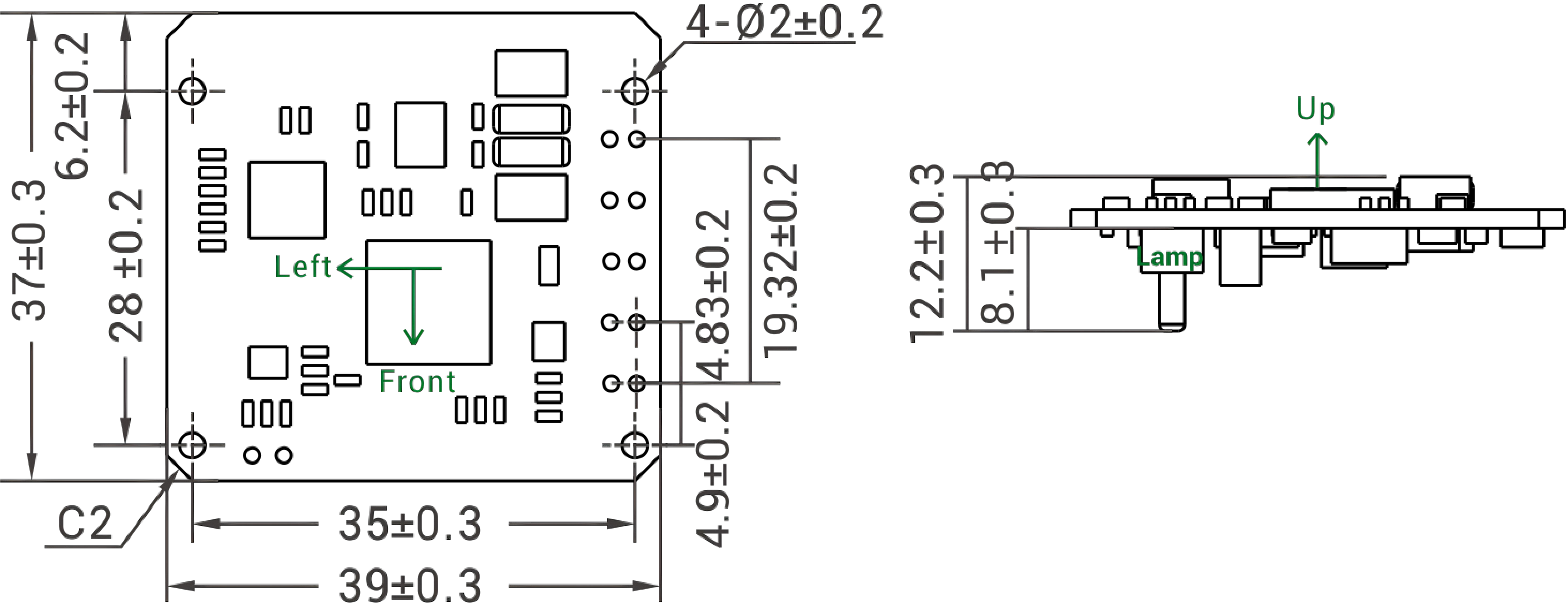
PCBA Dimension Diagram
PCBA size: L39×W37×H12.2mm
Installation size: L35×W28mm
Suggested screw: 4 M2 screws

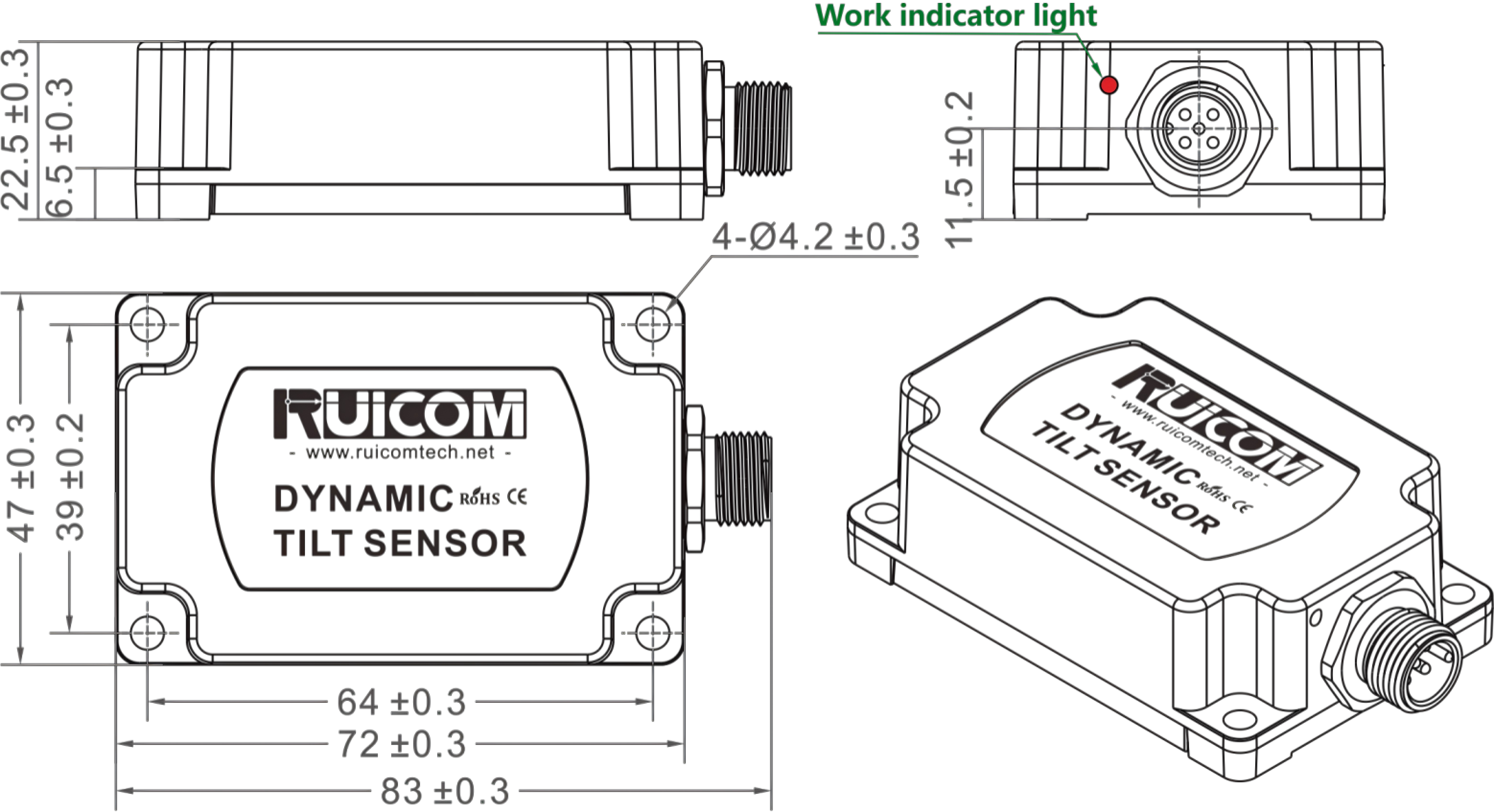
Single-head (male) connector housing dimension drawing
Shell Size: L83×W47×H22.5mm
Installation Size: L64×W39×H6.5mm
Shell material: aluminum alloy
Suggested screws: 4 M4 screws

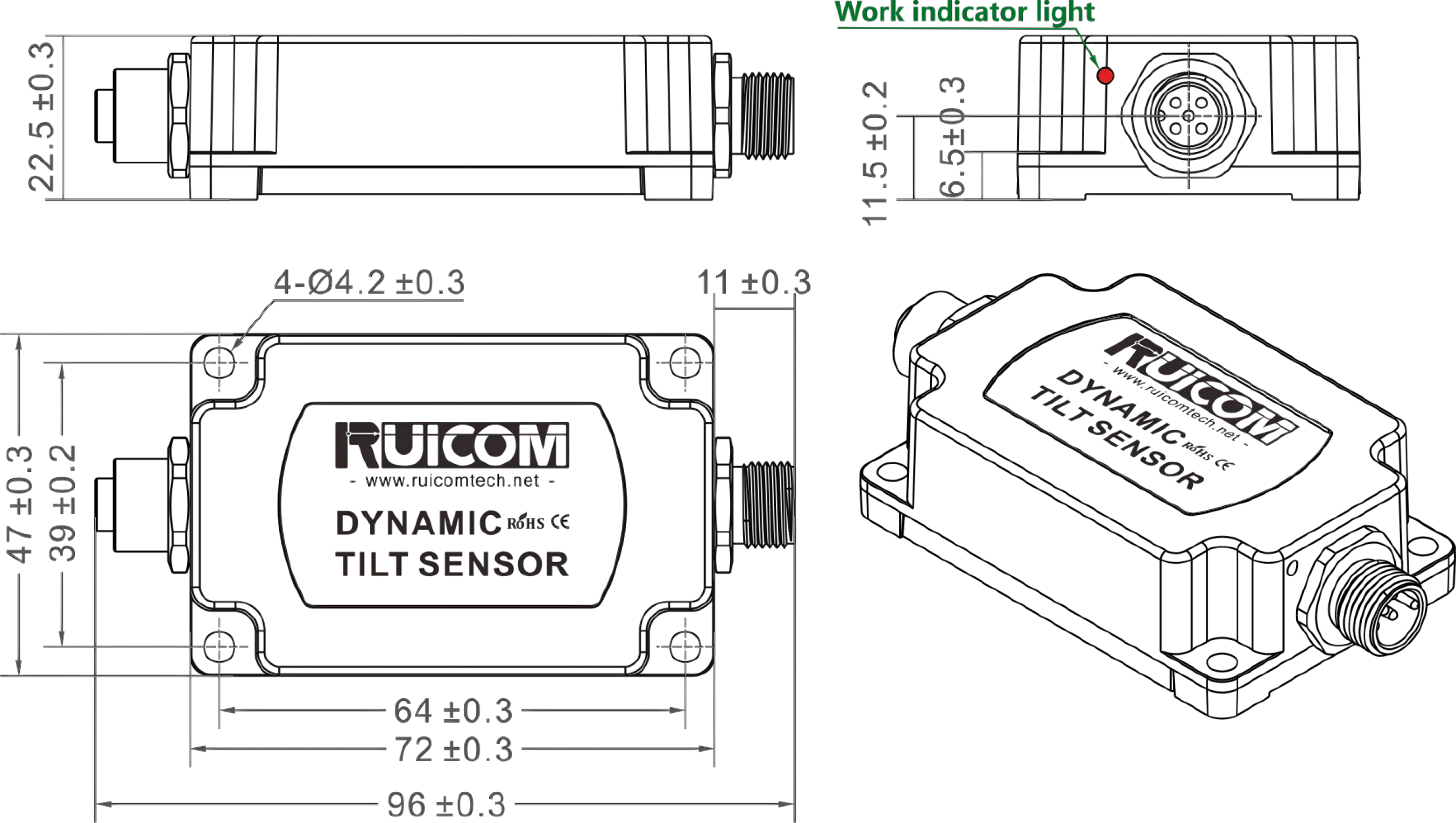
Double-headed connector Shell Size
Shell Size: L96×W47×H22.5mm
Installation Size: L64×W39×H6.5mm
Shell material: aluminum alloy
Suggested screws: 4 M4 screws

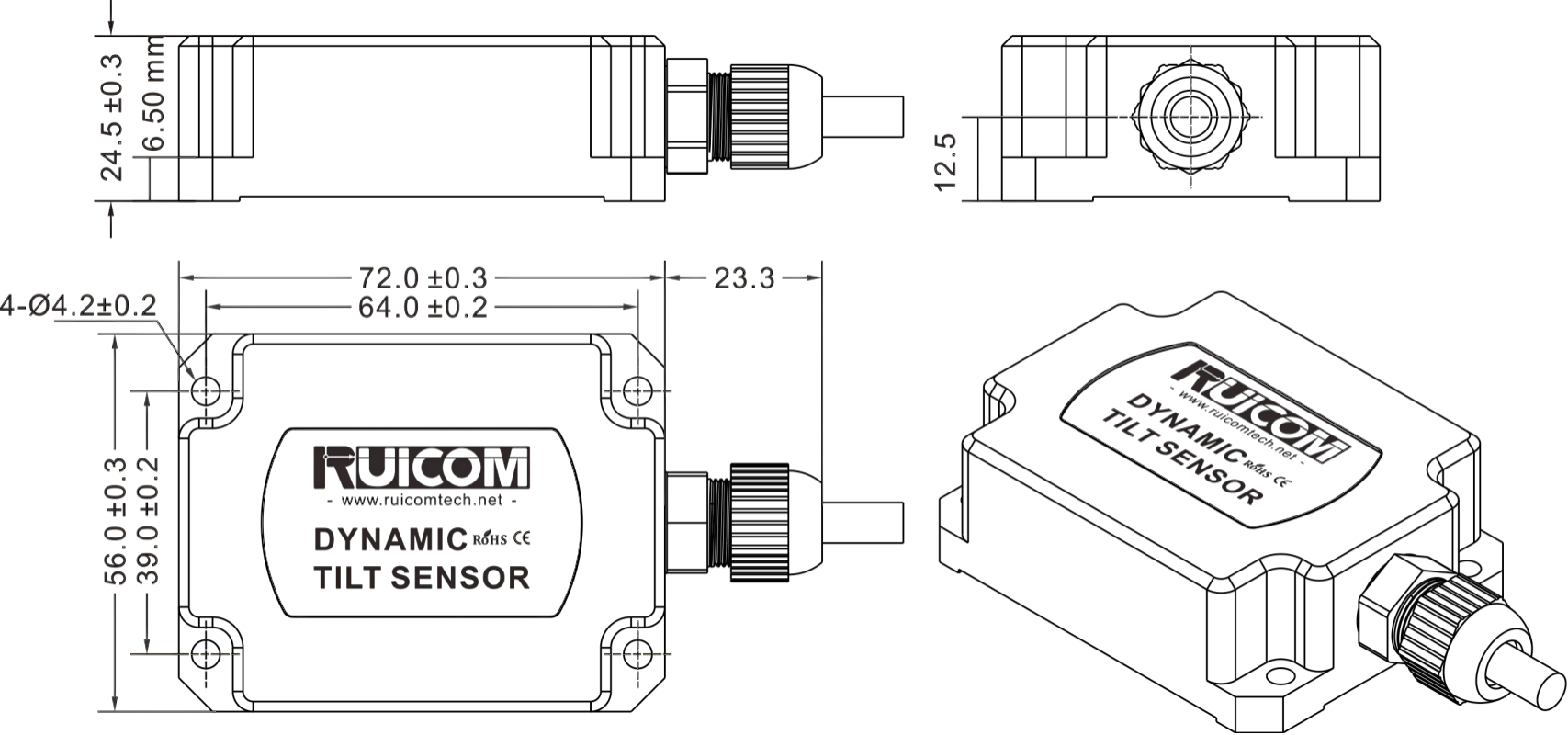
Corrosion-resistant shell size diagram
Shell Size: L95.3×W56×H24.5mm
Installation Size: L64×W39×H6.5mm
Shell material: 304 stainless steel
Suggested screws: 4 M4 screws