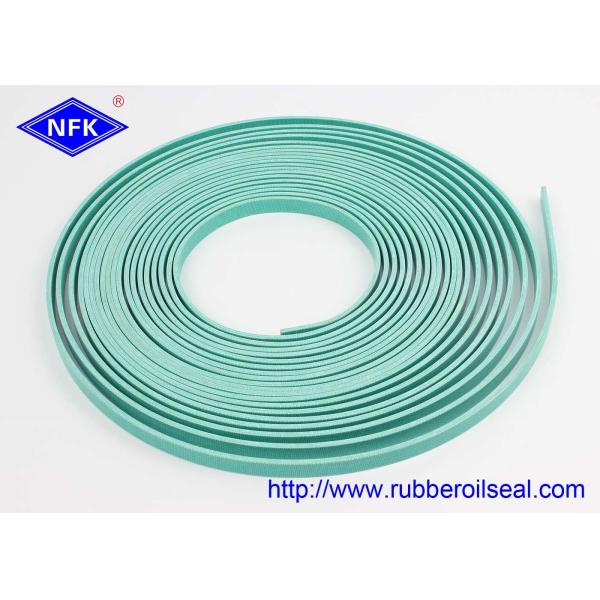
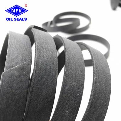
Custom Fabric Reinforced Phenolic Resin Wear Ring NFK WR 110x103x12 Hydraulic Cylinder Piston Guide Ring Anti-Friction Support Seal Ring
Professional Repair and Maintenance Information
Daily Maintenance and Upkeep Standards
- Regular Cleaning and Inspection: Conduct visual inspection every 300-500 hours of operation. Check for scratches, burrs, cracks, localized detachment, and abnormal wear. Clean impurities and dust from hydraulic oil to prevent particle adhesion and accelerated wear.
- Operating Condition Control: Avoid prolonged operation under overpressure, overtemperature, or uneven loads. Ensure smooth equipment start-up and shutdown, avoiding sudden impact loads. For extended shutdowns, clean cylinder interior to maintain lubrication.
- Lubrication and Protection: Apply suitable hydraulic system grease evenly to guide ring working surface during assembly and maintenance to maintain smooth sliding and reduce friction loss.
Common Faults and Repair Solutions
- Fault 1: Stuttering or sluggish cylinder movement - Clean guide ring and cylinder grooves, correct installation position. Minor deformation can be fine-tuned; severe wear requires replacement.
- Fault 2: Equipment vibration and abnormal noise - Inspect guide ring wear; replace if exceeds standard. Check cylinder and piston rod wear, clean system impurities.
- Fault 3: Localized cracking and surface peeling - Irreparable damage; replace with new custom-made guide ring. Check pressure and temperature control systems.
Disassembly and Replacement Precautions
Use gentle disassembly methods. Avoid prying or forceful striking. Clean sealing grooves and working surfaces before installation. Ensure perfect fit of WR 110x103x12 specification without twisting or misalignment. Test piston rod sliding smoothness before trial run.
Replacement Cycle Recommendations
- Normal light load conditions: Replace every 8000-10000 operating hours
- Heavy load, high-frequency conditions: Check and replace every 4000-6000 operating hours
Storage Requirements for Spare Guide Rings
Store in dry, cool, well-ventilated environment away from high temperatures, corrosive substances, oil stains, and sharp objects. Avoid compression deformation. Keep products flat; do not stack or apply heavy pressure.
WR Phenolic Reinforced Fabric Wear-Resistant Ring Installation Process
I. Pre-Installation Preparation
Required Tools & Supplies
NFK WR wear ring, 400# fine sandpaper, industrial cleaning solvent, lint-free rags, assembly plastic sleeve, rubber mallet, high-viscosity hydraulic lubricant, caliper, nitrile protective gloves, chamfer file
Component & Workpiece Inspection
Verify specifications: 110*103*12, NFK WR phenolic fabric wear ring; check no cracks, delamination, surface scratches or deformation.
Inspect piston groove: Remove all metal chips, old wear ring fragments and oil sludge. All groove inlet edges must have smooth chamfers (sharp edges will scratch phenolic fabric layers).
Check piston outer surface: No burrs, rust, pits or deep scratches; polish minor imperfections with fine sandpaper until smooth.
Cleaning
Thoroughly wipe the piston surface and sealing groove with cleaning solvent, fully dry to eliminate metal debris that causes abrasion.
II. Lubrication Treatment
Coat the inner and outer circumferential surfaces of the NFK WR phenolic wear ring evenly with hydraulic lubricant.
Apply a thin layer of lubricant inside the piston mounting groove to reduce friction during press-fitting and prevent dry scraping damage.
III. Press-Fitting Installation Steps
Align the NFK WR wear ring with the piston end, slowly slide the ring onto the piston body, and move it to the target mounting groove.
Fit a plastic assembly sleeve over the wear ring outer diameter to avoid direct hammer impact on phenolic fabric surface.
Tap the sleeve uniformly around the circumference with a rubber mallet, steadily pushing the wear ring fully into the piston groove.
Confirm the wear ring sits completely flush inside the groove without tilting, protruding edges or twisting.
Slide the wear ring back and forth manually to test smooth movement, ensure no jamming or uneven tightness.
IV. Cylinder Assembly Process
Lubricate the inner wall of the cylinder barrel before assembly to reduce friction between wear ring and cylinder tube.
Keep the piston coaxial with the cylinder barrel, slowly push the piston assembly into the cylinder; avoid tilting or offset insertion that scrapes the phenolic wear ring.
Complete assembly of end cover, seals and locking parts, tighten bolts diagonally and evenly to maintain uniform concentricity.
V. Test Run Inspection
Conduct low-pressure no-load reciprocating movement of the piston several times, check for abnormal friction noise.
Gradually raise hydraulic pressure to rated working pressure, perform continuous reciprocating test.
Check temperature rise and surface abrasion of the wear ring; no abnormal heat or scratch marks means installation is qualified.
VI. Critical Installation Notes & Forbidden Operations
Never use metal screwdrivers, steel hammers or sharp tools to pry the wear ring — phenolic resin fabric is easy to crack and peel.
Installation without chamfered groove edges is prohibited; sharp corners will cut the fabric reinforcement layer.
Dry assembly without lubricant will cause severe surface scratching and early failure of the wear ring.
Do not stretch or bend the wear ring excessively during fitting; permanent deformation leads to uneven guiding clearance.
Storage rules: Keep wear rings away from high temperature, strong acid and direct sunlight; discard deformed, cracked or delaminated products.
VII. Common Fault Troubleshooting After Installation
Abnormal friction noise during operation: Insufficient lubrication, piston tilt during assembly, burrs left on cylinder bore.
Fast surface wear of wear ring: Metal debris remained in groove, sharp chamfer edges, mismatched assembly clearance.
Wear ring falls out of groove: Not fully pressed into the groove, groove size tolerance out of range.
Piston stuck inside cylinder: Over-compressed deformed wear ring, unbalanced bolt tightening causing piston offset.