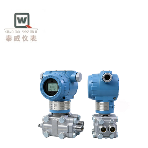
Absolute Pressure Transmitter with Double Chamber Vacuum Reference Design
1. What is an Absolute Pressure Transmitter?
In industrial pressure measurement, the choice of reference point determines whether your readings have physical meaning—or just approximate values. When engineers monitor vacuum distillation columns, pharmaceutical lyophilization chambers, or semiconductor vacuum coating processes, they need pressure values referenced against a true zero point, not the fluctuating atmospheric pressure outside the building.
A gauge pressure transmitter references ambient atmosphere. On a day with high barometric pressure, your "vacuum" reading shifts by several millibars—enough to compromise process validation in regulated industries. An absolute pressure transmitter solves this by sealing a high-vacuum reference cavity against which all measurements are compared. The result: readings that remain accurate regardless of weather, elevation, or ambient pressure changes.
This is critical for:
- Vacuum systems — where even ±1 mbar drift can ruin semiconductor wafer yields or pharmaceutical batch consistency
- Absolute pressure measurement — required for vapor pressure analysis, distillation control, and thermodynamic calculations
- Atmospheric pressure influence elimination — essential for processes at high altitudes or in weather-sensitive applications
2. Working Principle of Double Chamber Absolute Pressure Transmitter
The double chamber architecture represents a distinct engineering approach to absolute pressure measurement. Rather than a single-cavity sensor with an integrated vacuum reference, this design separates the measurement and reference functions into two dedicated chambers connected through a precision sensor diaphragm.
High pressure chamber (H side): Process pressure enters through a robust isolation diaphragm. Fill fluid (typically silicone oil or inert fluorocarbon) hydraulically transmits pressure to the central sensing diaphragm. The isolation diaphragm protects the sensor from direct contact with process media—critical for corrosive, high-temperature, or particle-laden fluids.
Low pressure vacuum chamber (L side): During manufacturing, this chamber is evacuated to below 10⁻⁴ Pa and hermetically sealed. This permanent vacuum serves as the absolute zero reference. Unlike gauge pressure instruments that reference ambient air, this sealed vacuum eliminates the single largest source of measurement uncertainty in vacuum applications.
Sensor diaphragm: The central sensing element—typically a piezoresistive silicon chip or a capacitive cell—detects the differential between process pressure (H side) and the vacuum reference (L side). Since the L side is effectively zero absolute pressure, the sensor output directly represents absolute pressure.
Pressure signal output: The sensor's raw signal (mV for piezoresistive, pF for capacitive) is conditioned by the transmitter electronics into a standard industrial output—4-20 mA with HART protocol, or digital fieldbus (FOUNDATION Fieldbus, PROFIBUS PA). The onboard microcontroller applies temperature compensation, linearization, and range configuration before final output.
3. Double Chamber Structure Advantages
The double chamber design is not merely a manufacturing choice—it directly impacts measurement quality, operational reliability, and total cost of ownership across the instrument's service life.
- Vacuum reference stability: The separate vacuum chamber is physically isolated from the process connection. Unlike single-chamber designs where the vacuum reference shares space with fill fluid, the double chamber architecture prevents contamination of the reference vacuum by outgassing fill fluids or hydrogen permeation through thin diaphragms. Industry data shows drift rates below 0.1% of URL per 5 years for well-manufactured double chamber transmitters, versus 0.2-0.3% for single-chamber equivalents.
- High static pressure capability: The dual-chamber structure distributes mechanical stress more evenly. The process side chamber can be reinforced independently of the reference side, enabling designs rated for static pressures exceeding 40 MPa (400 bar) without compromising vacuum integrity.
- Measurement accuracy: With a stable vacuum reference unaffected by process conditions, the double chamber transmitter achieves baseline accuracy of ±0.075% of span or better. The symmetrical chamber design also provides inherent compensation for ambient temperature effects on both sides of the sensor.
- Long-term reliability: The hermetic sealing of the vacuum chamber eliminates moisture ingress, oxidation of internal components, and reference degradation—common failure modes in instruments with vented reference sides. MTBF (Mean Time Between Failure) figures exceed 200 years for properly installed units.
- Harsh industrial environment suitability: With no vent to atmosphere, the instrument is immune to humidity, corrosive atmospheric gases (H₂S, SO₂ in refineries), dust ingress, and insect blockage—all issues that plague gauge pressure transmitters with atmospheric reference ports. The fully sealed design achieves IP66/IP67 protection ratings as standard.
Common Measurement Challenges & Solutions
| Customer Operating Condition | Legacy Approach Limitations | Our Solution | End Benefit |
|---|
| Vacuum tank pressure measurement — operating at 1-100 mbar absolute |
Gauge pressure transmitters show daily drift of 5-20 mbar due to barometric changes. Operators compensate manually with correction tables. |
Double chamber absolute transmitter with 0-1.6 bar(a) range, ±0.075% accuracy, vacuum reference sealed below 10⁻⁴ Pa |
Stable readings within ±0.12 mbar regardless of weather. Eliminated manual corrections. Batch consistency improved 40%. |
| Chemical reactor absolute pressure monitoring — 200°C process, hydrogen-containing atmosphere |
Standard absolute transmitters suffer hydrogen permeation through thin diaphragms, causing 2-5% annual zero drift. Requires quarterly recalibration. |
Gold-coated Hastelloy C-276 diaphragm with double chamber design. Thick isolation diaphragm (0.1 mm vs industry standard 0.05 mm) minimizes permeation. |
Annual drift reduced to <0.15%. Recalibration interval extended from quarterly to biennial. Process safety margin increased. |
| Distillation column vacuum measurement — 50 mbar abs, fluctuating ambient temperature (-15°C to +45°C) |
Single-chamber transmitters show 0.3-0.5% zero shift across ambient temperature range due to differential thermal expansion between sensor and reference. |
Symmetrical double chamber design with matched 316L stainless steel construction. Both chambers experience equal thermal expansion, canceling temperature effects. |
Temperature coefficient reduced to <0.05%/10K. Column pressure control accuracy improved from ±2 mbar to ±0.5 mbar. Product purity increased. |
| Pharmaceutical process pressure control — SIP sterilization at 135°C, FDA 21 CFR Part 11 compliance required |
Conventional transmitters lack sterile process connections and cannot withstand repeated steam sterilization cycles without reference drift. |
Tri-Clamp hygienic connection, electropolished Ra ≤ 0.4 μm diaphragm, fully sealed double chamber rated for 150°C continuous with digital audit trail capability via HART |
Survives 500+ SIP cycles without drift deviation. FDA-compliant electronic records reduce validation documentation effort by 60%. |
Application Cases
Case 1: Fine Chemical Vacuum Distillation
Industry: Fine Chemicals / Solvent Recovery
Application: Vacuum distillation column absolute pressure control for heat-sensitive organic intermediates
Medium: Mixed organic solvents (toluene, methanol, acetone) with trace acid
Pressure Range: 10-100 mbar absolute
Operating Temperature: 150°C process, 180°C during cleaning cycles
Installation Environment: Outdoor chemical plant, coastal location with high humidity and salt spray, Zone 2 hazardous area
Customer Challenge: Existing gauge pressure transmitters required daily zero checks against a portable vacuum gauge. Ambient pressure changes between morning and afternoon caused 15-30 mbar apparent drift. Product boiling point would shift, affecting distillate purity.
Previous Problem: Three to four batches per month failed purity specifications due to undetected pressure deviations. Annual cost of off-spec product exceeded $85,000. Manual correction process took 45 minutes per shift.
Solution: Installed double chamber absolute pressure transmitter with remote diaphragm seal and 3-meter capillary. Gold-coated Hastelloy diaphragm for acid resistance. Configured 0-200 mbar(a) range with HART digital output to DCS.
Installation Location: 1.5 meters from column vapor line, with cooling neck to protect transmitter electronics.
Result: Absolute pressure control accuracy ±0.3 mbar. Zero manual interventions required over 18 months. Off-spec batches reduced to zero. ROI achieved in 4 months through reduced waste and labor savings. Column throughput increased 12% due to optimized vacuum profile.
Case 2: Semiconductor Wafer Processing
Industry: Semiconductor Manufacturing
Application: PVD (Physical Vapor Deposition) chamber absolute pressure monitoring during sputtering process
Medium: Argon gas at ultra-low pressure with trace metal vapor
Pressure Range: 10⁻³ to 10 mbar absolute
Operating Temperature: 25-80°C chamber environment
Installation Environment: Class 100 cleanroom, vibration-sensitive area adjacent to wafer handling robots
Customer Challenge: The sputtering process requires precise argon pressure control at 5 × 10⁻³ mbar. Even 1% pressure deviation changes film deposition rate and uniformity. Existing capacitance manometers drifted 0.5-1.0% per month due to metal vapor contamination of the reference cavity.
Previous Problem: Monthly recalibration required, with 4-6 hours downtime each session. Wafer yield fluctuations of 3-5% traced to pressure measurement instability. Annual cost of yield loss: $500,000+.
Solution: Double chamber absolute pressure transmitter with Inconel 718 isolation diaphragm, integrated baffle to prevent metal vapor deposition on diaphragm surface. Dual-redundant sensor configuration with automatic deviation alert at 0.25% difference.
Installation Location: Direct-coupled to chamber KF-40 flange port, with flexible bellows connection to isolate robot-induced vibration.
Result: Drift reduced to <0.1% per 6 months. Recalibration interval extended to semi-annual. Wafer yield stabilized at 98.5% ±0.3%. Payback period: 2.5 months. Instrument replacement interval extended from 2 years to projected 8+ years.
Case 3: Pharmaceutical Freeze-Drying (Lyophilization)
Industry: Pharmaceutical / Biotechnology
Application: Freeze-dryer chamber absolute pressure measurement during primary and secondary drying phases
Medium: Water vapor and nitrogen atmosphere
Pressure Range: 0.05-1.0 mbar absolute
Operating Temperature: -50°C to +40°C chamber; 121°C during SIP sterilization
Installation Environment: GMP cleanroom Grade B, full CIP/SIP compatibility required, FDA 21 CFR Part 11 data integrity requirements
Customer Challenge: The lyophilization cycle's end point is detected by pressure rise test—closing the isolation valve and monitoring pressure increase. Pirani gauges used previously had non-linear response and gas-composition dependency (respond differently to water vapor vs nitrogen), causing premature or delayed cycle endpoints.
Previous Problem: 8% of batches had incorrect endpoint determination. Over-drying degraded heat-sensitive biologics; under-drying caused stability failures. FDA 483 observation cited inadequate process monitoring instrumentation.
Solution: Double chamber absolute pressure transmitter with heated sensor housing (45°C maintained) to prevent water vapor condensation. 0-2 mbar(a) range, ±0.5% of reading accuracy. HART protocol with digital data logging to SCADA meeting 21 CFR Part 11 audit trail requirements.
Installation Location: Chamber side port with steam-sterilizable diaphragm seal, ASME BPE compliant surface finish.
Result: Pressure rise endpoint detection accuracy improved 5x. Batch rejection rate reduced from 8% to 0.3%. FDA warning letter resolved. Annual savings in reduced product loss and investigation costs: $320,000. Instrument validated for 200+ SIP cycles without drift.
Case 4: Power Plant Condenser Vacuum Monitoring
Industry: Thermal Power Generation
Application: Steam turbine condenser back-pressure absolute measurement for heat rate optimization
Medium: Steam/water mixture with non-condensable gases (air, CO₂)
Pressure Range: 30-120 mbar absolute (typical condenser operating range)
Operating Temperature: 30-50°C normal; up to 80°C during upset conditions
Installation Environment: Power plant turbine hall, high vibration (2-5 mm/s), ambient temperature 25-55°C, moderate dust
Customer Challenge: Condenser back-pressure directly affects turbine heat rate—every 10 mbar increase costs approximately 0.5% in fuel efficiency. Existing gauge pressure transmitters fluctuated ±8 mbar daily with ambient pressure changes, making it impossible to trend true condenser performance. Operators couldn't distinguish between real vacuum degradation and atmospheric effects.
Previous Problem: Delayed detection of condenser tube fouling by 2-3 weeks because trend data was masked by barometric noise. Annual fuel penalty estimated at $180,000 for a 300 MW unit. Cooling water pump optimization impossible without reliable absolute pressure data.
Solution: Double chamber absolute pressure transmitter, 0-200 mbar(a) range, stainless steel housing with IP67 protection. Installed with a condensate pot and impulse line slope to prevent water accumulation. Dual output: 4-20 mA to DCS and HART digital for asset management system trending.
Installation Location: Condenser neck at turbine exhaust, with 2-meter impulse line and isolation valve manifold for in-situ calibration checks.
Result: Condenser absolute pressure trend data now clean of barometric interference. Tube fouling detected within 2-3 days instead of 2-3 weeks. Optimized cleaning schedule saved $95,000/year in fuel costs. Cooling water pump VFD control implemented based on reliable pressure data, saving additional $45,000/year in auxiliary power. Instrument still within 0.1% of original calibration after 3 years.
Why Choose Our Absolute Pressure Transmitter?
- Factory-sealed vacuum reference — Each unit undergoes helium leak testing and vacuum integrity verification during manufacturing. The reference cavity is evacuated below 10⁻⁴ Pa and hermetically sealed using electron beam welding, ensuring decades of measurement stability without reference degradation.
- Verified measurement accuracy — Every transmitter ships with a 5-point calibration certificate traceable to NIST/CNAS standards. Base accuracy of ±0.075% of calibrated span includes combined effects of linearity, hysteresis, and repeatability per IEC 60770.
- Corrosion-resistant material options — Isolation diaphragms available in 316L stainless steel, Hastelloy C-276, Monel 400, Tantalum, and gold-coated variants. Process flanges in 316L, Hastelloy, or PTFE-lined configurations address the full spectrum of chemical compatibility requirements.
- Hydrogen permeation mitigation — For hydrogen-rich processes (refinery hydrotreaters, ammonia plants), optional gold-plated diaphragm and thickened isolation membrane reduce hydrogen permeation by 90% compared to standard 316L diaphragms, eliminating a common source of long-term zero drift.
- Wide ambient temperature compensation — Compensated from -40°C to +85°C with total temperature effect less than ±(0.08% URL + 0.1% span) per 20°C change. Suitable for direct outdoor installation without additional thermal protection in most climate zones.
- Field-configurable range — Turndown ratio up to 100:1 allows a single 10 bar(a) transmitter model to be configured for any measurement span from 0.1 to 10 bar(a). Adjustable via local pushbuttons or HART communicator without recalibration.
- Industrial communication compatibility — Standard 4-20 mA with HART 7 protocol. Optional FOUNDATION Fieldbus ITK 6, PROFIBUS PA Profile 3.02, or Modbus RTU (RS-485). All digital protocols support remote configuration, diagnostic data access, and multi-variable output (pressure + sensor temperature).
- Safety certification portfolio — ATEX/IECEx Ex ia IIC T4 Ga (intrinsic safety), Ex d IIC T6 Gb (flameproof), and SIL 2/3 certification per IEC 61508. Suitable for installation in Zone 0, Zone 1, and Zone 2 hazardous areas.
- Integrated overpressure protection — Mechanical stops protect the sensor diaphragm against accidental overpressure up to 4× the rated range on the H side without calibration shift. The sealed vacuum chamber is isolated from process overpressure events.
- 10-year stability guarantee — Long-term drift specification of ≤±0.15% of URL over 10 years, verified through accelerated life testing per IEC 60770. Reduces recalibration frequency and associated maintenance costs.
Technical Specifications
Measurement Range0-0.1 bar(a) to 0-100 bar(a), configurable via 100:1 turndown
Reference Accuracy±0.075% of calibrated span (standard); ±0.04% optional
Long-term Stability≤±0.15% of URL / 10 years
Output Signal4-20 mA (2-wire) with HART 7; optional FF/PB/Modbus
Power Supply10.5-45 VDC (standard); 10.5-32 VDC (Ex ia)
Process Connection1/2" NPT, M20×1.5, G1/2; flange options DN25-DN80
Wetted Materials (Diaphragm)316L SST, Hastelloy C-276, Monel 400, Tantalum, Gold-plated
Wetted Materials (Housing)316L SST process flange; 304 SST electronics housing
Operating Temperature (Process)-40°C to +120°C (direct mount); up to +400°C with remote seals
Operating Temperature (Ambient)-40°C to +85°C (LCD readable -30°C to +70°C)
Pressure ReferenceSealed vacuum (<10⁻⁴ Pa), verified by helium leak test
Protection GradeIP66/IP67 per IEC 60529; NEMA 4X
Turndown Ratio100:1 (range continuously adjustable)
Response Time≤100 ms (T63); damping adjustable 0-60 s
CertificationsATEX, IECEx, SIL 2/3, CE, EAC, NEPSI
Local DisplayOptional backlit LCD with bar graph; 360° rotatable housing
Frequently Asked Questions
Q: What is the difference between absolute pressure and gauge pressure?
Absolute pressure is measured relative to a perfect vacuum (zero pressure), while gauge pressure is measured relative to the current atmospheric pressure. This means a gauge pressure reading of 0 bar(g) at sea level equals approximately 1.013 bar(a). This distinction becomes critical in vacuum applications: a vessel at 0.5 bar(a) absolute pressure is under partial vacuum, but a gauge pressure transmitter at sea level would show approximately -0.513 bar(g). If the same gauge transmitter were installed at a facility at 2,000 meters elevation (where atmospheric pressure is ~0.795 bar), it would show roughly -0.295 bar(g) for the identical physical condition. Absolute pressure transmitters eliminate this ambiguity, providing readings that are physically meaningful regardless of installation location or weather conditions.
Q: Can a differential pressure transmitter measure absolute pressure?
Yes—and this is precisely the operating principle of a double chamber absolute pressure transmitter. A standard differential pressure (DP) transmitter measures the difference between two process connections (H and L sides). To measure absolute pressure, the L side is permanently sealed under high vacuum during manufacturing, creating a stable zero reference. The transmitter then effectively measures: P_absolute = P_H - P_vacuum(reference) ≈ P_H, since the vacuum reference is effectively zero. This approach has a key advantage: it leverages the proven reliability and wide availability of DP transmitter platforms while delivering absolute pressure measurement capability. However, not all DP transmitters can be configured this way—the vacuum seal integrity and long-term stability of the reference cavity must be specifically engineered for this application, with proper materials selection and manufacturing processes to prevent vacuum degradation over the instrument's service life.
Q: Why is vacuum reference stability important for absolute pressure measurement?
The vacuum reference cavity inside an absolute pressure transmitter serves the same role as a "zero point" in any measurement system. If the zero drifts, every reading derived from it is systematically wrong. In a double chamber absolute transmitter, the vacuum reference is typically evacuated to below 10⁻⁴ Pa (0.0000001% of atmospheric pressure). Even a tiny leak—whether through microscopic seal defects, hydrogen permeation through the metal diaphragm, or outgassing of internal materials—can raise the reference cavity pressure over time. When this happens, the transmitter under-reads absolute pressure by the amount of reference degradation. For example, if the reference drifts from 10⁻⁴ Pa to 100 Pa over years of service, every reading will be approximately 1 mbar too low. In pharmaceutical freeze-drying where process pressures of 0.05-1 mbar are typical, this level of drift would render the instrument useless. The double chamber design mitigates this risk by physically separating the process and reference chambers, reducing the pathways for vacuum degradation.
Q: Where are absolute pressure transmitters used in industrial applications?
Absolute pressure transmitters are essential in applications where the process must be controlled independently of atmospheric conditions. Key sectors include: (1) Chemical and petrochemical — vacuum distillation columns, reactor pressure monitoring, vapor recovery systems, and hydrogenation processes where pressure compensated for barometric changes is critical for reaction kinetics. (2) Pharmaceutical and biotechnology — freeze-drying (lyophilization), sterile processing, and fermentation where validated absolute pressure data is a regulatory requirement. (3) Semiconductor manufacturing — sputtering, CVD, and etch processes requiring sub-millibar vacuum control for consistent wafer quality. (4) Power generation — steam turbine condenser back-pressure monitoring directly affects heat rate calculations and plant efficiency optimization. (5) Food processing — vacuum evaporation, freeze concentration, and modified atmosphere packaging. (6) Research and calibration — as transfer standards for calibrating other pressure instruments against an absolute reference. In all these sectors, the common thread is the need for pressure measurements that are physically absolute—immune to the daily barometric fluctuations that introduce 20-50 mbar errors in gauge pressure instruments.
Q: How does temperature affect absolute pressure transmitter accuracy?
Temperature influences absolute pressure transmitters through two mechanisms: (1) Thermal expansion of fill fluid between the isolation diaphragm and the sensing element causes a zero shift of typically 0.05-0.15% URL per 10°C for remote seal configurations. This is managed by using low-expansion fill fluids (silicone oil DC200, fluorocarbon) and minimizing fill fluid volume through short capillaries. (2) The sensor element itself has a temperature coefficient—silicon piezoresistive sensors exhibit sensitivity changes of ~0.05%/°C, while capacitive sensors show lower effects (~0.02%/°C). Both are compensated digitally using polynomial correction algorithms calibrated during manufacturing. The double chamber design provides an additional advantage: symmetric thermal expansion of the matched chambers cancels a significant portion of the temperature effect. A well-designed transmitter with active temperature compensation maintains total temperature error within ±(0.08% URL + 0.1% span) per 20°C across the compensated range of -40°C to +85°C, making it suitable for outdoor installation in most climate zones without additional thermal shielding.
Q: What is the typical turndown ratio for an absolute pressure transmitter?
Modern intelligent absolute pressure transmitters offer turndown ratios ranging from 20:1 for basic models to 100:1 for premium instruments. A 100:1 turndown means a single transmitter with an upper range limit (URL) of 10 bar(a) can be configured to measure any span between 0.1 bar(a) and 10 bar(a). For example, the same transmitter model could measure 0-0.5 bar(a) for a vacuum distillation column, 0-5 bar(a) for a reactor, or 0-10 bar(a) for a storage vessel. This flexibility provides significant inventory reduction benefits: fewer transmitter models need to be stocked as spares, and the same transmitter can be repurposed across different applications within a plant. However, accuracy specifications apply to the configured span, not the URL. A ±0.075% of span accuracy on a 100:1 turndown configuration means ±0.075% of 0.1 bar(a) = ±0.075 mbar—demanding excellent sensor signal-to-noise ratio at low spans. The double chamber design supports high turndown ratios because the vacuum reference remains stable regardless of the configured measurement span.
Q: How often should an absolute pressure transmitter be calibrated?
Calibration intervals depend on the application criticality, operating environment, and instrument specifications. For general industrial applications with double chamber absolute transmitters having ±0.075% accuracy and ≤0.15%/10 year stability specifications, annual verification is typical, with full recalibration only when verification exceeds tolerance. In regulated industries (pharmaceutical, aerospace), documented calibration intervals of 6-12 months are standard to meet quality system requirements. High-integrity safety applications (SIL 2/3 loops) typically require annual proof testing. However, field experience shows that well-maintained double chamber absolute transmitters often remain within specification for 3-5+ years between recalibrations, particularly when installed with proper impulse line design, and not exposed to extreme temperature cycling or corrosive atmospheres. We recommend an initial verification at 6 months after installation to establish a baseline drift trend, then extending intervals based on observed performance. The vacuum reference stability is the determining factor—if the reference cavity maintains integrity, the transmitter's long-term drift will be dominated by electronics drift rather than sensor degradation.
Q: What are the key considerations for installing an absolute pressure transmitter in vacuum service?
Vacuum installation requires attention to several details often overlooked in positive-pressure installations. (1) Impulse line design: Lines must slope continuously downward toward the process connection (minimum 1:10 slope) to prevent condensate pockets. Even a 10 cm water column in an impulse line creates ~10 mbar error—significant when measuring 50 mbar absolute. (2) Leak integrity: All fittings, valves, and gaskets in the impulse line must be vacuum-rated. Standard compression fittings may leak at sub-atmospheric pressures. Helium leak testing of the complete installation is recommended for sub-100 mbar applications. (3) Outgassing: Avoid PTFE tape as a thread sealant in vacuum lines—it outgasses and can raise local pressure. Use vacuum-grade sealants or metal-to-metal seals. (4) Condensation: If process vapors can condense in impulse lines, consider heated impulse lines or direct-mount configurations with remote seals. Liquid in impulse lines creates a hydrostatic head error that varies with fill level. (5) Vibration: Sensitive to vibration in high-vacuum ranges—use flexible connections or remote mounting. The double chamber transmitter's sealed reference makes it inherently better suited for vacuum service compared to gauge-referenced instruments that must maintain a clean, dry atmospheric vent path.
Q: How does hydrogen permeation affect absolute pressure transmitters, and how is it prevented?
Hydrogen permeation is a significant concern for absolute pressure transmitters in refinery, petrochemical, and ammonia plant applications. Hydrogen molecules, being extremely small (atomic radius ~25 pm), can diffuse through standard 316L stainless steel diaphragms at elevated temperatures (>100°C). When hydrogen reaches the fill fluid on the sensor side, it eventually migrates into the sealed vacuum reference cavity, raising the reference pressure and causing negative zero drift. The drift rate depends on hydrogen partial pressure, temperature, and diaphragm material—a standard 316L diaphragm in a 50 bar hydrogen process at 200°C may drift 2-5% URL per year. Mitigation strategies include: (1) Gold-coated diaphragms — a thin gold layer (~3 μm) deposited on the process side blocks hydrogen diffusion (gold has extremely low hydrogen permeability). This reduces permeation by 90-95%. (2) Thicker diaphragms — increasing from the standard 0.05 mm to 0.1-0.15 mm increases the diffusion path length proportionally. (3) Alternative diaphragm materials — Hastelloy C-276 offers better hydrogen permeation resistance than 316L, though not as effective as gold coating. (4) Remote seals with intermediate barrier fluids — in extreme cases, a dual-seal configuration with a hydrogen getter material in the intermediate cavity can capture permeated hydrogen before it reaches the vacuum reference.
Q: What output signals and communication protocols are available for absolute pressure transmitters?
The industry standard is 4-20 mA analog output with superimposed HART (Highway Addressable Remote Transducer) digital communication. This configuration provides backward compatibility with existing analog control systems while enabling digital access to configuration, diagnostics, and multi-variable data (pressure, sensor temperature, electronics temperature) through a HART communicator or asset management system. For greenfield projects and modern control systems, fully digital fieldbus options include: FOUNDATION Fieldbus H1 (31.25 kbit/s, ITK 6 certified) supporting device descriptions, function blocks, and alert reporting; PROFIBUS PA (Profile 3.02) for integration with Siemens and other PROFIBUS-based DCS platforms; and Modbus RTU over RS-485 for direct integration with PLCs and RTUs without the need for analog input cards. Some manufacturers also offer wireless options (WirelessHART per IEC 62591) for locations where cable installation is impractical—though power must still be supplied, typically through long-life battery packs or energy harvesting. When selecting a protocol, consider: existing control system compatibility, the need for multi-variable data access, distance limitations (HART: 3 km max, FF: 1.9 km max), and cybersecurity requirements for networked instruments.