Smart 19 Inch Rack Mounted Telecom Power System AC to -48V DC Output 13 Intelligent Circuit Breakers for Base Station and Outdoor Cabinet with RS485 Remote Monitoring
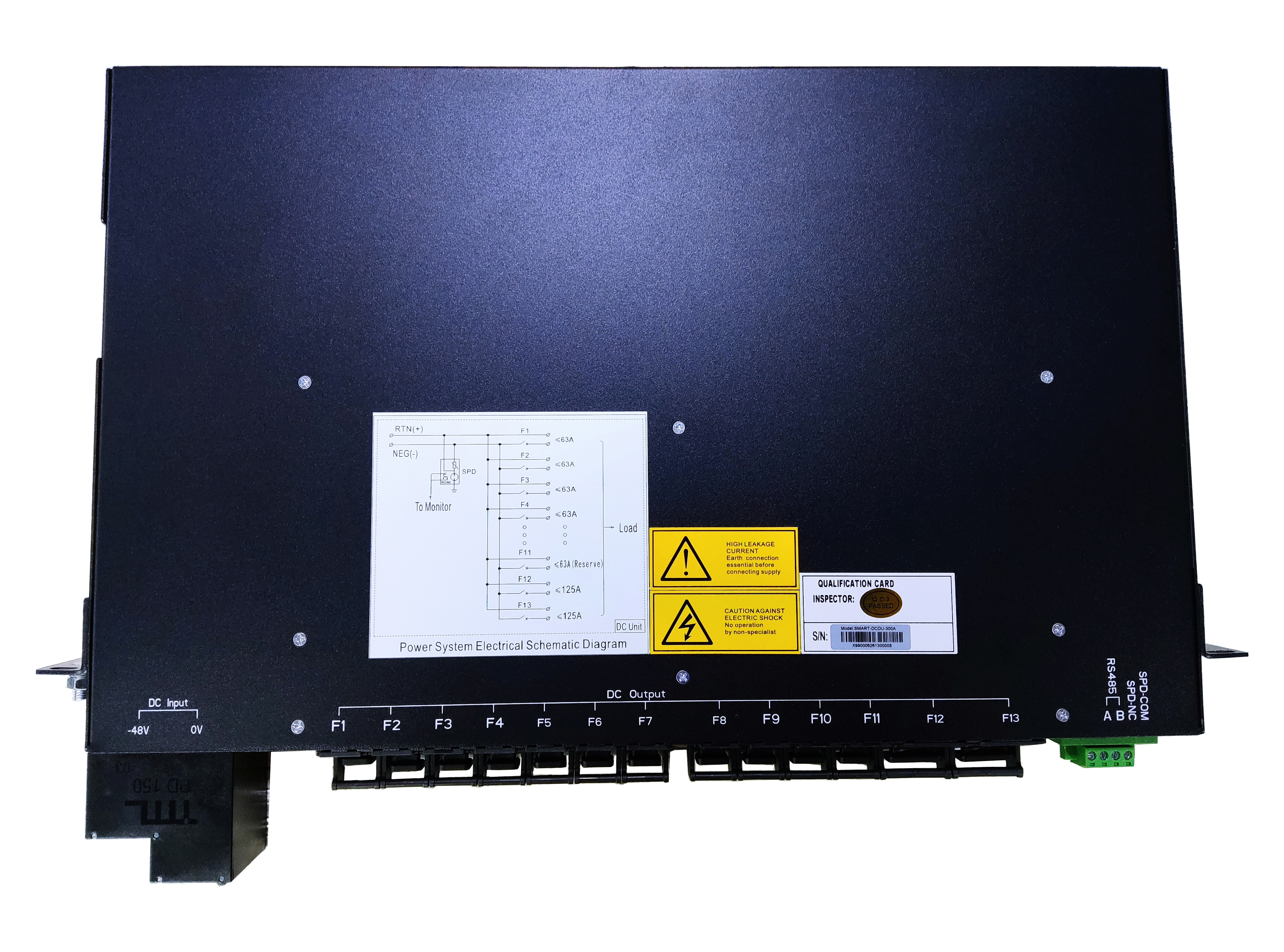
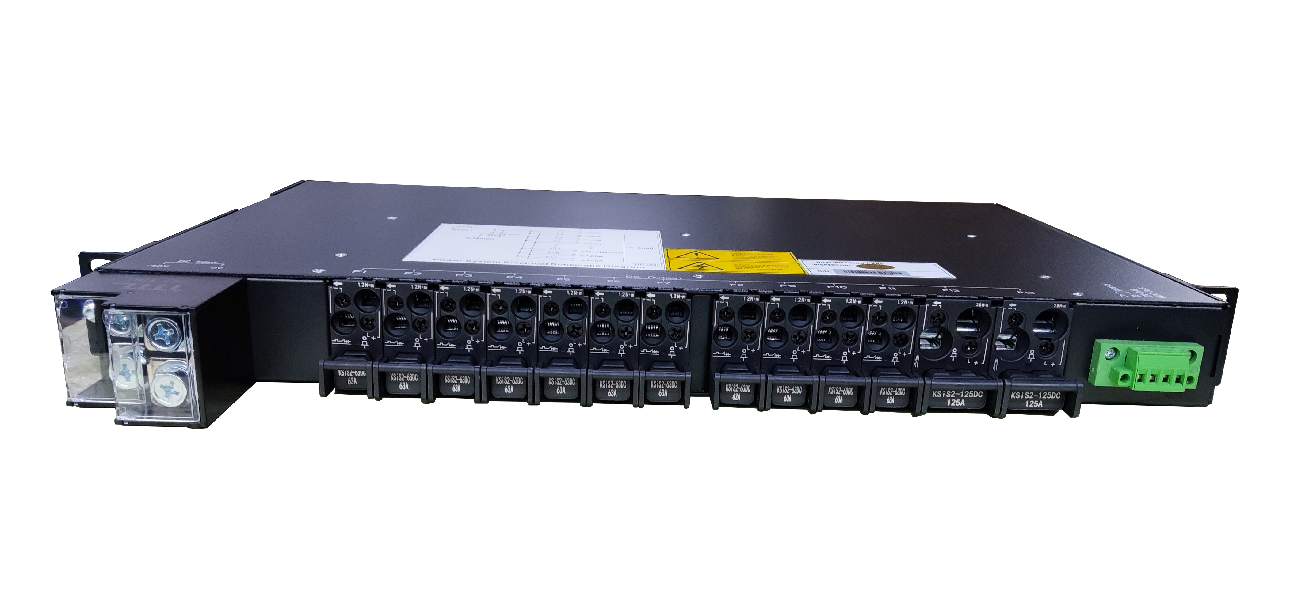
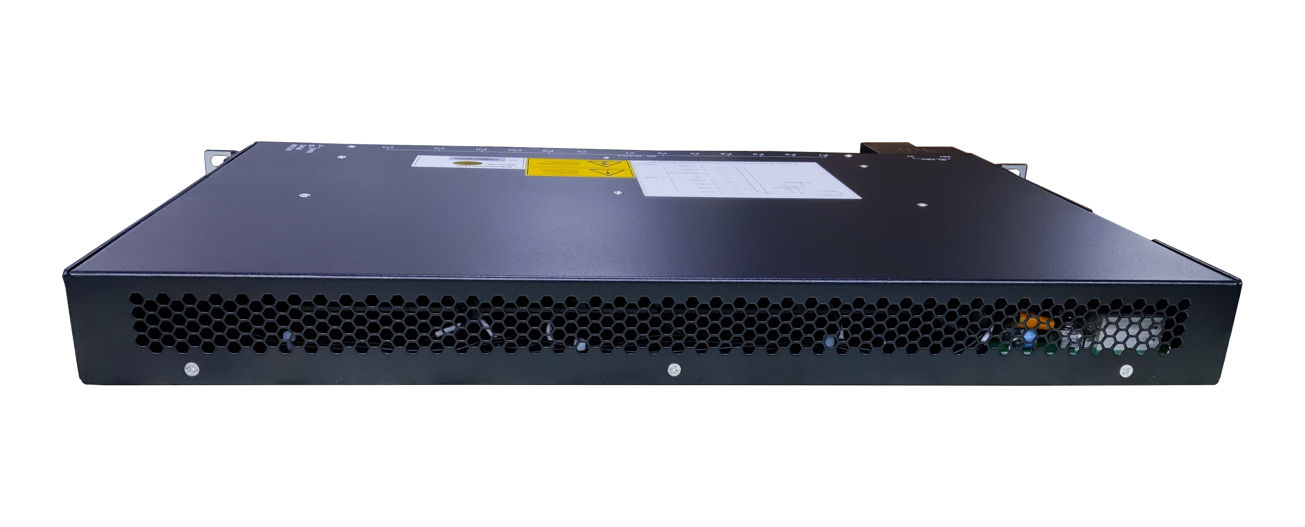
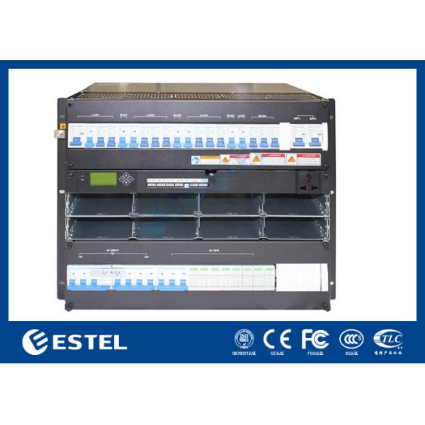
This is a compact 19-inch rack-mounted telecom power system engineered to convert and manage DC power for telecom applications. It integrates AC rectification, DC load distribution, and intelligent monitoring into a single unit. The system delivers reliable -48V DC power to various telecom loads through 13 individually controlled intelligent circuit breaker outputs. It features a robust black metal chassis, clear schematic labeling, and transparent protective covers on the input terminals to ensure operational safety.
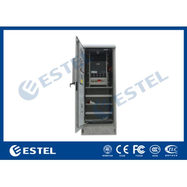
Widely utilized in telecom macro and micro base stations, outdoor telecom cabinets, and network nodes to provide centralized -48V DC power distribution to radio units, transmission equipment, and routers. It is also ideal for railway communication systems and other industrial DC power backup infrastructure.
Input Voltage: AC 220V (Rectifier Input), -48V DC (Battery Input)
Input Configuration: Single AC input terminal and single DC battery terminal.
Output Configuration: 13 independent intelligent circuit breaker outputs (F1 to F13).
Circuit Breaker Ratings Available: 16A and 32A, tailored for varying load capacities.
Monitoring Interface: RS485 port for remote monitoring support (requires connection to MC2900 controller).
Mounting Type: Standard 19-inch rack mount form factor.
Integrated Power Management: Combines AC rectification and DC distribution in a single chassis, simplifying site power architecture.
Intelligent Load Control: The 13 output intelligent circuit breakers allow for individual control of each circuit, enabling remote on/off operations and granular load management.
Enhanced Safety: Input terminals are covered with transparent plastic housings, preventing accidental electrical contact during maintenance.
Remote Diagnostics Support: The integrated RS485 interface supports remote monitoring when connected to a compatible controller (e.g., MC2900), allowing for immediate remote fault alerts and breaker switching.
Installation: Mount the unit into the 19-inch rack rails of the telecom cabinet, securing it firmly using the side mounting brackets.
Input Connection: Connect the AC power cable to the rectifier input terminal. Connect the -48V battery cables to the DC input terminal, ensuring strict polarity correctness. Tighten the screws and secure the transparent protective covers.
Output Connection: Route the DC output cables to your telecom equipment. Insert the intelligent circuit breakers and adjust their amperage (A) ratings based on the specific load requirements of each device.
Monitoring Setup: Connect the RS485 terminal block to the main power frame equipped with an MC2900 controller. The main power frame is then linked to the remote control platform, enabling status monitoring and switch control for each individual breaker.
Testing: Perform a final power-on test to check for correct voltage at each output terminal and verify the communication link with the monitoring system.