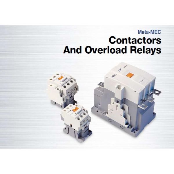
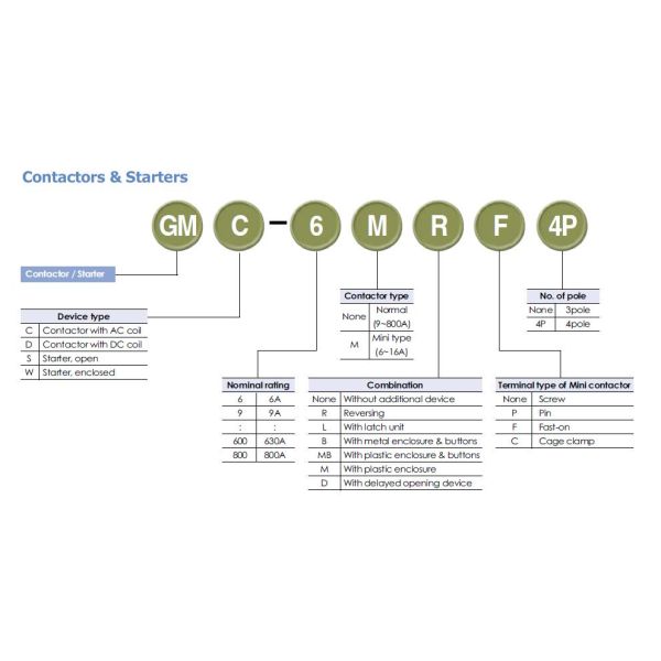
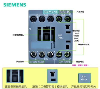
LS GMC Contactor 3P, 4P 9A,12A,18A,32,40A,50A,65A,75A,85A, AC-3 AC-1 Coil Voltage 24V,110V,230V,380V
characteristic
 • Current range 09~85A;
 • AC, DC control coil is optional;
 • Different types of starters are available: standard motor start contactors, reversible contactors, star-delta starters, autotransformer starters, etc.
 • Optional connection: bolt connection (09~8000A);
 • Product Certification: CCC, CE, CCS;
 Advantage
 • Compact installation
 > Surge suppressor installation requires no tools and can be inserted directly into the contactor without taking up more space
 > Reversible contactor is only 90mm wide, mechanical interlocking does not take up extra space, installation takes almost no time
 > Starter components provide pre-wired modules for quick and easy assembly
 • Highly integrated
 > to 100A contactor integration 1 normally open / 1 normally closed auxiliary contact
 > DC coil with built-in bidirectional suppression diode
 > Reversible contactor group with built-in bidirectional suppression diode
 • Safe and reliable
 > The main circuit and control circuit of the control and protection components are clearly distinguished
 > Mirrored contact design that meets safety standards, ensuring 10 million reliable actions
 > Protective cover prevents accidental contact of the contactor
 • outstanding quality
 > DC coils have a wide range of control voltages (0.7~1.25Uc)
 > Strong earthquake resistance
 > lower noise
 > Increased terminal strength
 
 > Permanent torque, reliable installation
 > Compact and space saving
 > Easy to install, saves time
> Easy to maintain and save costs
| Product Series |  			 Metal MEC  			 |  		
|---|---|
| product name |  			 AC Contactor  			 |  		
| product type |  			 Contactor  			 |  		
| Product short name |  			 GMC  			 |  		
| Contactor application area |  			 Applied to AC loads with a power factor greater than or equal to 0.95  			Squirrel cage motor for switching on and off normal start  |  		
| Use category |  			 AC-3  			AC-1 AC-4  |  		
| Number of poles |  			 3P  			 |  		
| Power pole contact composition |  			 3 NO  			 |  		
| Rated working voltage [Ue] |  			 Power circuit: <= 690 V AC 25...400 Hz  			Power circuit: <= 300 V DC  |  		
| Rated operating current [Ie] |  			 18 A 60 °C) on <= 440 V AC AC-3 Applicable power circuit  			32 A 60 °C) on <= 440 V AC AC-1 for power supply circuit  |  		
| Motor power (kW) |  			 4 kW on 220...230 V AC 50/60 Hz (AC-3)  			7.5 kW on 380...400 V AC 50/60 Hz (AC-3) 9 kW on 415...440 V AC 50/60 Hz (AC-3) 10 kW on 500 V AC 50/60 Hz (AC-3) 10 kW on 660...690 V AC 50/60 Hz (AC-3) 4 kW on 400 V AC 50/60 Hz (AC-4)  |  		
| Motor power HP (UL / CSA) |  			 1 hp on 115 V AC 50/60 Hz for 1-phase motors  			3 hp on 230/240 V AC 50/60 Hz for 1-phase motors 5 hp on 200/208 V AC 50/60 Hz for 3-phase motors 5 hp on... 230/240 V AC 50/60 Hz for 3-phase motors 10 hp on 460/480 V AC 50/60 Hz for 3-phase motors 15 hp on 575/600 V AC 50/60 Hz for 3-phase motors  |  		
| Control loop characteristics |  			 AC on 50/60 Hz  			 |  		
| Control loop voltage |  			 230 V AC 50/60 Hz  			 |  		
| Auxiliary contact type |  			 1 NO + 1 NC  			 |  		
| Rated impulse withstand voltage [Uimp] |  			 6 kV in accordance with IEC 60947  			 |  		
| Overvoltage category |  			 III  			 |  		
| Conventional heating current [Ith] |  			 10 A on <60 °C for signal circuit  			32 A on <60 °C for power supply circuit  |  		
| Rated turn-on capability [Irms] |  			 140 A AC suitable signal circuit in accordance with IEC 60947-5-1  			250 A DC suitable signal loop in accordance with IEC 60947-5-1 300 A on 440 V applicable power supply circuit in accordance with IEC 60947  |  		
| Rated breaking capacity |  			 300 A on 440 V applicable power supply circuit in accordance with IEC 60947  			 |  		
| Rated short-time withstand current [Icw] |  			 145 A on <40 °C - 10 s for power supply circuit  			240 A on <40 °C - 1 s for power supply circuit 40 A on <40 °C - 10 minutes for power circuit 84 A on <40 °C - 1 minute for power circuit 100 A - 1 s for signal circuits 120 A - 500 ms Applicable signal loop 140 A - 100 ms for signal circuits  |  		
| Fuses used with relays |  			 10 A gG Applicable signal circuit in accordance with IEC 60947-5-1  			50 A gG on...<= 690 V with type 1 for power supply circuit 35 A gG on ...<= 690 V with type 2 for power supply circuit  |  		
| Average impedance |  			 2.5 mΩ - Ith 32 A 50 Hz for power supply circuits  			 |  		
| Rated insulation voltage [Ui] |  			 Power circuit: 690 V in accordance with IEC 60947-4-1  			Power circuit: 600 V CSA certification Power circuit: 600 V UL certification Signal loop: 690 V in accordance with IEC 60947-1 Signal loop: 600 V CSA certified Signal circuit: 600 V UL certification  |  		
| Electrical life |  			 1.65 kA2.s 18 A AC-3 Ue condition <= 440 V  			1 kA2.s 32 A AC-1 Ue condition <= 440 V  |  		
| Power consumption per pole |  			 2.5 W AC-1  			0.8 W AC-3  |  		
| Safety cover |  			 band  			 |  		
| Installation method |  			 Rail mounting  			Base plate installation  |  		
| standard |  			 CSA C22.2 No 14  			EN 60947-4-1 EN 60947-5-1 IEC 60947-4-1 IEC 60947-5-1 UL 508  |