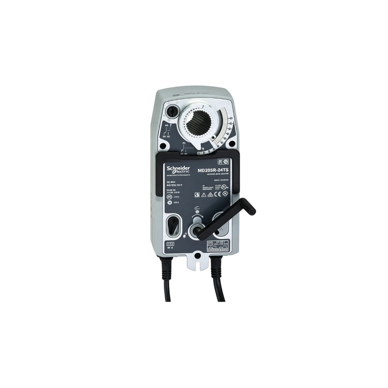
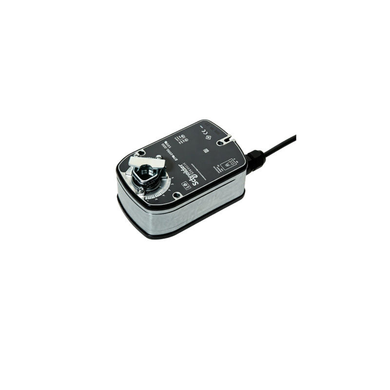
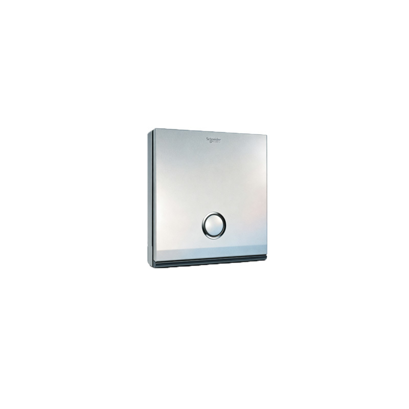
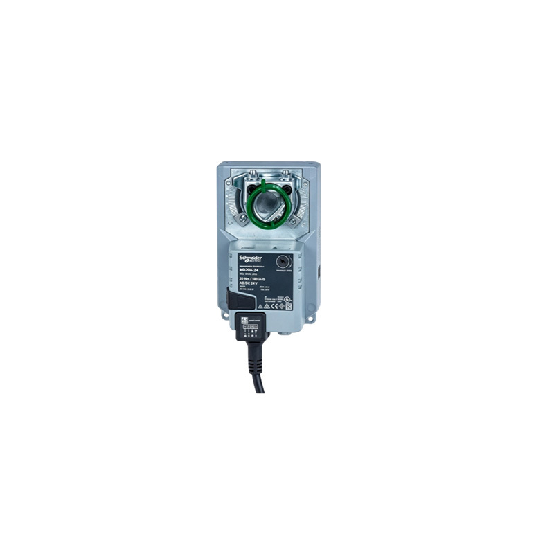
The L5504AMP is a DIN rail mounted analogue output unit for the Clipsal C-Bus control and management system. It provides four independent output channels that deliver a zero to ten volt DC signal to connected devices downstream.
This unit serves as the bridge between a lighting control network and the luminaires themselves, driving dimmable electronic ballasts and LED drivers that accept 0 to 10V control inputs. The four-channel design offers an optimal balance: dense enough to avoid needing individual devices per circuit, yet compact enough to remain economical for projects with small lighting groups.
Mounted on DIN rails within distribution boards, the unit allows low-voltage control wiring to exit the panel alongside mains circuits supplying the luminaires, keeping both functions together for commissioning and maintenance.
| Product Type | DIN rail mounted analogue output unit |
| Order Number | L5504AMP |
| System | Clipsal C-Bus control and management system |
| Output Channels | Four independent analogue output channels |
| Output Signal | 0 to 10 V DC per channel |
| Supply Voltage | 240 V AC |
| Mounting | DIN rail, four DIN modules wide |
| Dimensions | Approximately 72 mm wide, 85 mm high and 65 mm deep |
| Weight | Approximately 245 g |
| Intended Load | Dimmable ballasts and drivers with 0 to 10V control input |
| Network | C-Bus network connection to lighting control system |
| Installation Environment | Inside distribution board or enclosure |
| Typical Duty | Lighting level control from C-Bus network |
| Compliance | CE marking; RoHS and REACH declarations held by Schneider Electric |
Important Engineering Consideration: The 0 to 10V dimming interface controls lighting levels, not power. Mains supply to each luminaire must be independently switched and protected. Assuming the module turns lighting off can result in luminaires dimming to minimum but remaining faintly lit.
Control cables, while low voltage, are not immune to interference and should be run separately from mains conductors where practical. During commissioning, outputs should be verified channel by channel, as mis-mapped channels can appear as programming errors but are actually wiring issues.
Minimum and maximum levels require attention since drivers vary in their extinction points. A scene fading to zero may leave residual glow that cannot be resolved through C-Bus programming alone. When multiple modules share a board, record both C-Bus network load and addressing.